Table of Contents
Advertisement
Quick Links
WARNING: If the information in this manual is not
followed exactly, a fire or explosion may result causing
property damage, personal injury or loss of life.
— Do not store or use gasoline or other flammable va-
pors and liquids in the vicinity of this or any other
appliance.
— WHAT TO DO IF YOU SMELL GAS
• Do not try to light any appliance.
• Do not touch any electrical switch; do not use any
phone in your building.
• Immediately call your gas supplier from a neighbor's
phone. Follow the gas supplier's instructions.
• If you cannot reach your gas supplier, call the fire
department.
— Installation and service must be performed by a quali-
fied installer, service agency or the gas supplier.
INSTALLER: Leave this manual with the appliance.
CONSUMER: Retain this manual for future reference.
Questions, problems, missing parts? Before returning to your retailer, call
our customer service department at 1-855-607-6557, 8:00 am - 4:30 pm EST,
Monday through Friday or email info@factorybuysdirect.com
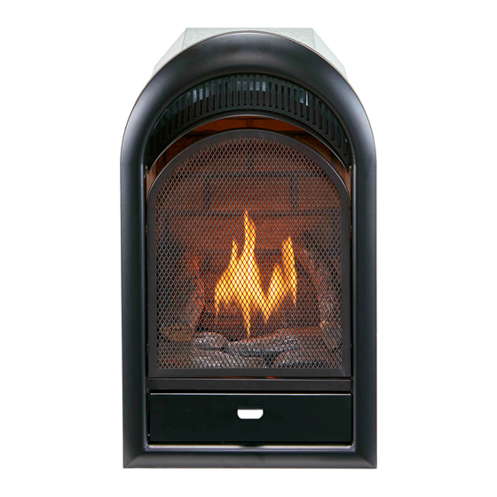
VENT-FREE GAS
FIREPLACE INSERT
OWNER'S OPERATION AND
INSTALLATION MANUAL
MODEL
FDF150T
PFS
®
US
Advertisement
Table of Contents

Related Manuals for Factory Buys Direct PFS FDF150T

Summary of Contents for Factory Buys Direct PFS FDF150T
- Page 1 VENT-FREE GAS FIREPLACE INSERT OWNER’S OPERATION AND INSTALLATION MANUAL MODEL FDF150T ® WARNING: If the information in this manual is not followed exactly, a fire or explosion may result causing property damage, personal injury or loss of life. — Do not store or use gasoline or other flammable va- pors and liquids in the vicinity of this or any other appliance.
-
Page 2: Table Of Contents
TABLE OF CONTENTS Safety ............3 Operation ..........18 Qualified Installing Agency ......4 Inspecting Burners........21 Specifications ..........5 Care And Maintenance ......22 Product Features ........5 Troubleshooting ........24 Local Codes..........5 Parts ............28 Unpacking..........6 Replacement Parts ........ -
Page 3: Safety
SAFETY IMPORTANT: Read this owner’s WARNING: Young children manual carefully and completely should be carefully supervised before trying to assemble, op- when they are in the same room erate, or service this heater. as the appliance. Toddlers, Improper use of this heater can young children and others may cause serious injury or death from be susceptible to accidental... -
Page 4: Qualified Installing Agency
SAFETY 8. Do not use heater if any part has been WARNING: You must operate under water. Immediately call a qualified this heater with screen in place. service technician to inspect the room heater and to replace any part of the Any safety screen or guard control system and any gas control which removed for servicing an appli-... -
Page 5: Specifications
SPECIFICATIONS Model FDF150T Gas Type Natural Gas Propane Gas Maximum Input Rating 15,000 Btu/Hr 15,000 Btu/Hr Minimum Input Rating 7,000 Btu/Hr 11,000 Btu/Hr Pressure Regulator Setting 4" W.C. 9" W.C. Max. 10" Max. 14" Inlet Gas Pressure* (inches of water) Min. -
Page 6: Unpacking
UNPACKING 1. Remove top inner pack. 7. Remove log set by cutting plastic ties. 2. Tilt carton so that heater is upright. 8. Carefully unwrap log. 3. Remove protective side packaging. 9. Check for any shipping damage. If heater or log is damaged, promptly inform your 4. -
Page 7: Air For Combustion And Ventilation
AIR FOR COMBUSTION AND VENTILATION WARNING: This heater shall WARNING: This heater shall not be installed in a confined space not be installed in a room or or unusually tight construction space unless the required vol- unless provisions are provided ume of indoor combustion air for adequate combustion and is provided by the method de-... - Page 8 AIR FOR COMBUSTION AND VENTILATION VENTILATION AIR Ventilation Air From Inside Building Ventilation Air From Outdoors Provide extra fresh air by using ventilation This fresh air would come from an adjoining grills or ducts. You must provide two perma- unconfined space. When ventilating to an nent openings: one within 12"...
-
Page 9: Installation
INSTALLATION IMPORTANT: Vent-free heaters add moisture NOTICE: This heater is intended to the air. Although this is beneficial, installing for use as supplemental heat. heater in rooms without enough ventilation air Use this heater along with your may cause mildew to form too much moisture. primary heating system. - Page 10 INSTALLATION GAS SELECTION Insert Gas Fitting Insert Gas Fitting This appliance is factory for Propane Gas for Natural Gas preset for propane gas. No changes are required for connecting to propane. Only a qualified installer or service tech- nician can perform gas selection and connecting to gas supply.
- Page 11 INSTALLATION 2. Apply thread sealant to the threads on Use only the cap supplied on the the connection fitting. While pushing in, regulator. Do not use an off the rotate the fitting clockwise until the threads shelf pipe plug. This can damage engage the regulator.
- Page 12 INSTALLATION BUILT-IN FIREPLACE INSTALLATION WARNING: Do not allow any combustible materials to overlap the firebox front. WARNING: Do not allow combustible or noncombustible materials to cover any necessary openings like louvered slots. 1/4" Clearance to Facia WARNING: Never modify or 3/8"...
- Page 13 INSTALLATION 3. Attach gas line to fireplace gas regulator. See Connecting to Gas Supply, page 14. 4. Check all gas connections for leaks. See 90° Checking Gas Connections, page 16. IMPORTANT: When finishing your firebox, combustible materials such as wall board, gypsum board, sheet rock, drywall, plywood, etc, must have 1/2"...
- Page 14 INSTALLATION CONNECTING TO GAS SUPPLY WARNING: A qualified ser- CAUTION: Avoid damage to vice technician must connect regulator. Hold gas regulator heater to gas supply. Follow all with wrench when connecting local codes. into gas piping and/or fittings. WARNING: This appliance CAUTION: Use pipe joint requires a 3/8"...
- Page 15 INSTALLATION The installer must supply an external regula- Install sediment trap in supply line as shown tor. The external regulator will reduce incom- in Figure 11. Place sediment trap where it is ing gas pressure. You must reduce incoming within reach for cleaning. Place sediment trap gas pressure to between 11"...
- Page 16 INSTALLATION CHECKING GAS CONNECTIONS Test Pressures Equal To or Less Than WARNING: Test all gas piping 1/2 PSIG (3.5 kPa) and connections for leaks after 1. Close equipment shutoff valve (see Fig- installing or servicing. Correct ure 15). all leaks at once. 2.
- Page 17 INSTALLATION PRESSURE TESTING HEATER GAS CONNECTIONS 1. Open equipment shutoff valve (see Figure 17, page 16). Apply a noncorrosive leak 15, page 16). detection fluid to all joints. Bubbles form- ing show a leak. 2. Open main gas valve located on or near gas meter for natural gas or open propane 5.
-
Page 18: Operation
INSTALLATION BATTERY INSTRUCTIONS CAUTION: Do not dispose of batteries in fire, batteries may explode or leak. Battery • Battery is included. Positive • Remove battery when depleted. • Be sure to observe proper polarity (+/-) when installing or replacing the battery. Damage due to improper battery installation may void the warranty on the product. - Page 19 OPERATION LIGHTING INSTRUCTIONS Note: If pilot does not stay lit, refer to WARNING: You must oper- Troubleshooting, pages 24 though 27. ate this heater with the screen Also contact a qualified service technician in place. Make sure screen is or gas supplier for repairs. Until repairs are made, light pilot with match.
- Page 20 OPERATION THERMOSTAT CONTROL OPERATION The thermostatic control used on this model room temperature drops below the set tem- differs from standard thermostats. Standard perature. The control knob can be set to any thermostats simply turn the burner on and off. comfort level between HIGH (5) and LOW (1).
-
Page 21: Inspecting Burners
INSPECTING BURNERS IMPORTANT: Owner’s should check pilot flame pattern and burner flame pattern often. Incorrect flame patterns indicate the need for cleaning (see Care and Maintenance, page 22) or service. WARNING: Only a qualified service person should service and repair heater. This includes maintenance requiring replacement or alteration of components. -
Page 22: Care And Maintenance
CARE AND MAINTENANCE WARNING: Turn off heater and let cool before servicing. CAUTION: You must keep control areas, burner, and circulating air passageways of heater clean. Inspect these areas of heater before each use. Have heater inspected yearly by a qualified service techni- cian. - Page 23 CARE AND MAINTENANCE ODS/PILOT Ignitor Natural Gas Thermocouple CAUTION: Never use a wire, Electrode Burner needle, or similar object to clean Propane Gas Burner ODS/pilot. This can damage ODS/ pilot unit. Use a vacuum cleaner, pressurized air, or a Pilot Air small, soft bristled brush to clean.
-
Page 24: Troubleshooting
TROUBLESHOOTING WARNING: If you smell gas: • Shut off gas supply. • Do not try to light any appliance. • Do not touch any electrical switch; do not use any phone in your building. • Immediately call your gas supplier from a neighbor’s phone. Fol- low the gas supplier’s instructions. - Page 25 TROUBLESHOOTING Problem Possible Cause Corrective Action When ignitor button is 1. Ignitor electrode is posi- 1. Replace electrode. pressed in, there is no tioned wrong. Ignitor elec- spark at ODS/pilot trode is broken. 2. Ignitor electrode is not con- 2. Replace ignitor cable nected to ignitor cable.
- Page 26 TROUBLESHOOTING Problem Possible Cause Corrective Action Burner(s) does not light 1. Burner orifice is clogged. 1. Clean burner orifice (see after ODS/pilot is lit Care and Maintenance, page 22) or replace burner orifice. 2. Burner orifice diameter is too 2. Replace burner orifice. small.
- Page 27 TROUBLESHOOTING Problem Possible Cause Corrective Action Heater produces a click- 1. Metal is expanding while 1. This is common with most ing/ticking noise just after heating or contracting while heaters. If noise is exces- burner is lit or shut off. cooling.
-
Page 28: Parts
PARTS MODEL FDF150T www.factorybuysdirect.com 200200-01C... - Page 29 PARTS MODEL FDF150T This list contains replaceable parts for your heater. When ordering replacement parts, follow the instructions listed under Replacement Parts on page 30 of this manual. ITEM PART # DESCRIPTION **150PCS102B-01 Front Panel Assembly FDF150T1014-01 Bottom Door Panel F15T103B-01 Screen Assembly FE32A155B...
-
Page 30: Replacement Parts
• The replacement part number 1-855-607-6557 for referral information. ACCESSORIES To purchase heater accessories and parts call Factory Buys Direct at 1-855-607-6557. EQUIPMENT SHUTOFF VALVE For all models. Visit us online at www.factorybuysdirect.com for a complete selection of gas connection fittings. -
Page 31: Service Hints
You may feel your gas pressure is too low. If so, contact your local gas supplier. TECHNICAL SERVICE You may have further questions about installation, operation, or troubleshooting. If so, contact Factory Buys Direct at 1-855-607-6557. When calling, please have your model and serial numbers of your heater ready. www.factorybuysdirect.com... -
Page 32: Warranty
Factory Buys Direct makes no other warranties regarding this product. Factory Buys Direct’s liability is limited to the purchase price of the product and Factory Buys Direct shall not be liable for any other damages whatsoever under any circumstances including direct, indirect, incidental, or consequential damages.
Need help?
Do you have a question about the PFS FDF150T and is the answer not in the manual?
Questions and answers