Advertisement
Quick Links
Advertisement

Related Manuals for Haaga US-5


Summary of Contents for Haaga US-5
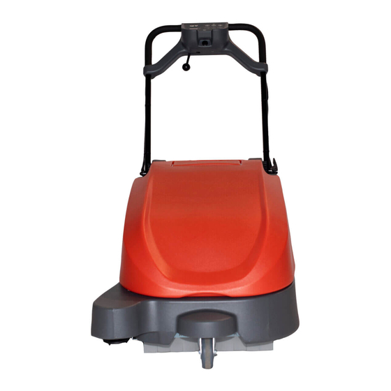
- Page 1 US-5 Battery Powered Push Sweeper Operator and Parts Manual...
-
Page 2: General Information
English Introduction Machine Data Please fill out at time of installation for future reference. This manual is furnished with each new model. It Model No. - __________________________________ provides necessary operation and maintenance Serial No. - __________________________________ instructions and replacement parts information. Installation Date - _____________________________ Read all instructions before using this machine. -
Page 3: Safety Label
English -Go slow on slippery surfaces. Onboard Battery Charger Information -Do not operate on inclines that exceed 2 %. The onboard battery charger's charging profile is -Do not use machine to transport people or specifically configured for a 12V sealed GEL battery. objects. - Page 4 (EN) Machine Components Vacuum, Side Brush, Main Brush Start Button Side Brush, Main Brush Start Button Vacuum, Main Brush Start Button Battery Discharge Indicator Hour Meter Battery Charger Cord Storage Compartment Battery Charger Outlet Adjustable Control Handle Adjustable Control Handle Lever Control Panel Main Power Button Side Brush...
- Page 8 ✓...
- Page 10 Pg. 19 Pg. 20...
-
Page 11: Control Panel
Control Panel LED Code Guide LED CODE REASON /FAULT SOLUTION One sweeping mode LED is solid Normal operating condition No action required One sweeping mode LED is Motor overload has shut down Disconnect battery cable and flashing fast machine due to obstruction. check main brush, side brush and fan. - Page 12 ✓...
- Page 13 > 15 kg /33 lbs...
- Page 14 ✓...
- Page 15 > 15 kg /33 lbs...
- Page 16 ✓ ✓ = > 15 kg /33 lbs...
- Page 17 ✓ ✓...
-
Page 20: Electrical Diagram
Electrical Diagram... - Page 21 Electrical Diagram IRIS Telemetry...
- Page 22 Parts List Fig. 1 – Wheel, Caster and Main Brush Assy...
-
Page 23: Parts List
Parts List Fig. 1 – Wheel, Caster and Main Brush Assy Ref. Part No. Description Qty. � US9010079 Wheel MTGKit ( Includes Wheel Bracket Qty2, Bracket Qty1, Caster Bracket Qty1, Bushings Qty4 & Mounting Hardware) � Screw, Soc, M6x1x45 � Washer, Flat M8 �... - Page 24 Parts List Fig. 2 – Side and Main Brush Drive Assy...
- Page 25 Parts List Fig. 2 – Side and Main Brush Drive Assy Ref. Part No. Description Qty. US9010173 Backet Kit Fan Battery ( Includes Brackets Batt Qty2, Bracket Fan Qty1, � Bracket Shaker Qty1, Bracket Brush Motor Qty1, AdjustmentPlate Qty1, Strap Qty1 & Mounting Hardware) Screw, Soc, M8x1.25x16 �...
- Page 26 Parts List Fig. 3 – Cover, Filter and Electrical Assy...
- Page 27 Parts List Fig. 3 – Cover, Filter and Electrical Assy Ref. Part No. Description Qty. � US9010173 Bracket Kit Fan Battery (Includes Brackets Batt Qty2, Bracket Fan Qty1, Bracket Shaker Qty1, Bracket Brush Motor Qty1, Switch Bracket Qty1, Strap Qty1, RubberMat Qty1 & Mounting Hardware) Screw, Soc M8x1,25x10 �...
- Page 28 Parts List Fig. 3 – Cover, Filter and Electrical Assy Describtion Ref. Part No. Qty. � Screw, Soc M5x0.8x12 Washer, flat M5 � Cord, Power, 16/3 BLK [2.5meter, NA] US1044067 Cord, Power, 1,0mm²/3BLK [2.5meter, AUS] US1026325 Cord, Power, 1,0mm²/3BLK [2.5meter, CHINA] US1026330 Cord, Power, BLK [KOR/CE] US1044068...
- Page 29 Parts List Fig. 4 – Handle Assy...
- Page 30 Parts List Fig. 4 – Handle Assy Ref. Part No. Description Qty. 9010181 Handle Rod & Lever Kit (Includes Lever Qty 1, Pipe LongQty1, Pipe Short Qty2, Rod Qty1 & Spring 6x22) � 9010034 Handle Hinge/Pivot Kit (Includes Hinge Outside Qty2, Hinge Inside Qty2, Plastic Disc Qty2, Cap Qty1 &...
- Page 31 Parts List Kit Content – Hardware Kit (Part No. 9013076) Ref. Part No. Description Qty. Retainment ring D=8 Retainment ring 8mm,square Retainment ring D=12 Spring, Tensioner, Brush Belt Spring, Propel...
- Page 32 Parts List Fig. 5 – Iris Telemetry Assy (Optional) Ref. Part No. Description Qty. 1069467 Control Box, Telem [USA, 3G] 09200 Screw, Pan, Phl, M5 x 0.80 x 12, ss 140011 Washer, Flat, 0.2180.45D.03,ss 09739 Nut, Hex, Lock, M5 x 0.80, nl, ss 1233236 Plate, Mount [IRIS Control Box] 1054683...
Need help?
Do you have a question about the US-5 and is the answer not in the manual?
Questions and answers