
Related Manuals for PNI MAB300


Summary of Contents for PNI MAB300
- Page 1 PNI MAB300 Swing gates opener Kit automatizare porti batante User manual ..........Manual de utilizare ........
- Page 3 Warnings Read this manual carefully before assembling and commissioning the » product. Incorrect installation and use can lead to product damage, personal injury and property damage. This product should be installed by qualified personnel only in compliance » with the safety rules. Installation by unskilled personnel leads to product malfunction and personal injury.
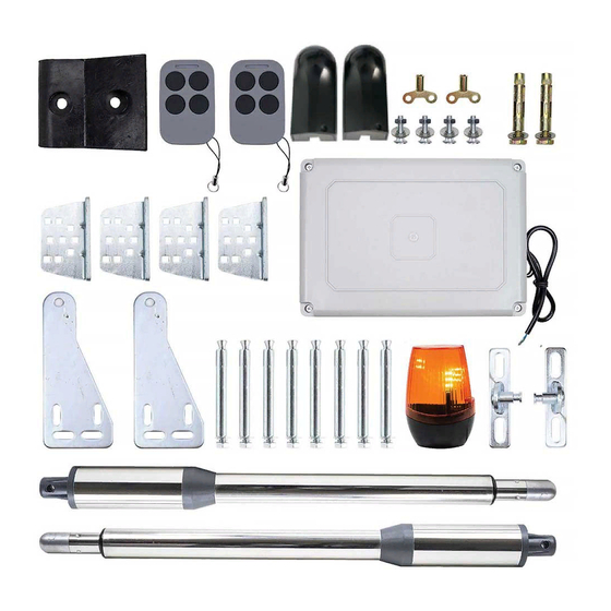
- Page 4 Included accessories Description of swing gate opener User manual...
- Page 5 1. Rear bracket 2. Front bracket 3. Extendable arm (300 mm) 4. Motor box 5. Power cable Open the gate manually 1. Gates 2. Manual spanner 3. Piston motor Release by spanner then lift it and separate the motor from the gates. User manual...
- Page 6 Functions In case of power failure: Use the manual spanner, separate the piston » motor from the gate and open or close the gates manually. When gate is obstructed: If, as they open, the gates encounter an » obstacle, they stop. Optional, the controller can be connected to a solar system, a warning »...
- Page 7 Technical specifications Supply voltage 230VAC±10% Motor voltage 24VDC 40W Rotation speed 200 rpm Maximum opening length 300 mm of the piston arm Piston elongation speed 1.6 cm/sec. Maximum length of a gate 2.5 m Maximum opening angle 110° Continuous operating time 5 min.
- Page 8 Rear brackets installation • Make 4 holes in the wall of 8 mm diameter. • Insert 4 concrete bolts (included in the package) into the holes. • Position and secure with the included screws the bracket for the piston motor. Note: If you have metal poles, you can weld the brackets.
- Page 9 Warnings Left image: the power cord and the drain hole are correctly positioned. Right image: incorrectly positioned power cord and drain hole. The power cord must not be above the engine body. In the opening motion of the gate, the cable could be caught and pinched presenting a risk of short circuiting.
- Page 10 1. Drill in the gate 2 holes of 10.2 mm each to a distance of 68 mm one from each other. 2. Fix the bracket in the holes. 3. Fix the motor piston to the front bracket using screws (these are not included as they vary depending on the thickness of the gate).
- Page 11 Sistem configuration Normal Closed Installation dimensions You can adjust the opening angle of the gate according to the dimensions in the table below: The values of columns A, B, C, E and L are expressed in mm. The values of column D are expressed in degrees. Control board wiring diagram Technical parameters: Power supply voltage of the control unit: 24 V.
- Page 12 9 10 11 12 13 14 15 16 17 18 1. 2SIDE: for connecting any external device that controls double gates 2. COM: for connecting the “ground” of external devices 3. 1SIDE: for connecting any external device that controls a single gate 4.
- Page 13 (counted from left to right) 21. and 22. The Motor2 Delay terminal is used to connect the motor 2 installed on the gate that first opens and then closes. Connect here the first blue wire (counted from left to right). NOTE: If used for a single gate, connect the motor to the Motor2 Delay terminal 23.
- Page 14 Settings After power on, digital display will self-check from 00-99 with buzzer sound. If indicator LED lights on, and the buzzer stops, it means the system is normal working condition. Basic operation Press and hold the FUN button until PO appears on the screen. You have now entered the settings menu.
- Page 15 P4 on the display, the device is set to the high speed stop force for the » Motor2. There are optional values from 0 to 20. After choosing the value, press the FUN button to save the data. (factory setting is 10). 3.
- Page 16 lights continuously until the door closes (~ 30s), then goes out. “1” - alarm in a monostable way, the lamp will only flash when the gate is in operation. “2” - the alarm is on a bistable model and the lamp lights continuously until the gate closes (~ 30s), then goes out.
- Page 17 Atentionari Cititi cu atentie acest manual inainte de montarea si punerea in functiune » a produsului. Instalarea incorecta poate duce la defectarea produsului, la ranirea personala si la distrugerea proprietatii. Acest produs trebuie instalat doar de catre personal calificat respectand »...
- Page 18 Continutul pachetului Descriere motor cu piston Manual de utilizare...
- Page 19 1. Suport fixare 2. Suport fixare 3. Brat de extindere (300 mm) 4. Cutie motor 5. Cablu de alimentare Deschiderea manuala a portii 1. Porti 2. Cheie manuala 3. Piston Eliberati pistonul folosind cheia manuala, ridicati pistonul, apoi separati pistonul de poarta. Manual de utilizare...
- Page 20 Functii In caz de intrerupere de curent: Folositi cheia manuala, separati motorul » cu piston de poarta si deschideti sau inchideti portile manual. Obstructionare porti: Daca in timp ce se deschid, portile intampina un » obstacol, se opresc. Optional, controller-ul poate fi conectat la un sistem solar sau la o baterie »...
- Page 21 Specificatii tehnice Tensiune de alimentare 230VAC±10%/ Tensiune motor 24VDC 40W Viteza de rotatie 200 rpm Deschidere maxima a bratului pistonului 300 mm Viteza de alungire a pistonului 1.6 cm/sec. Lungime maxima a unei porti 2.5 m Unghiul maxim de deschidere a portii 110°...
- Page 22 Instalare suporti pe stalpii portii • Faceti in zid 4 gauri cu un diametru de 8 mm. • Introduceti in gauri 4 dibluri de beton (incluse in pachet). • Pozitionati si fixati cu suruburile incluse suportul pentru motorul cu piston. Nota: In cazul in care aveti stalpi metalici si nu de zid, puteti suda suportul pentru motorul cu piston de...
- Page 23 Atentionari Imaginea din stanga: cablul de alimentare si orificiul de drenaj amplasate corect. Imaginea din dreapta: cablul de alimentare si orificiul de drenaj amplasate incorect. Cablul de alimentare nu trebuie sa stea deasupra corpului motorului. In miscarea de deschidere a portii, cablul ar putea fi prins si ciupit prezentand risc de scurtcircuit.
- Page 24 1. Faceti in poarta 2 gauri de 10.2 mm la o distanta de 68 mm una de alta. 2. Fixati suportul in gaurile din poarta. 3. Fixati capatul pistonului de suportul din poarta cu ajutorul unor suruburi (acestea nu sunt incluse intrucat variaza in functie de grosimea portii). 4.
- Page 25 Configurare sistem Normal Inchis (Normal Closed) Dimensiunile de instalare Puteti regla unghiul de deschidere a portii in functie de dimensiunile din tabelul de mai jos: Valorile coloanelor A, B, C, E si L sunt exprimate in mm. Valorile coloanei D sunt exprimate in grade. Diagrama conexiuni pe placa de baza Parametri tehnici: Tensiune de alimentare a unitatii de control: 24 V.
- Page 26 9 10 11 12 13 14 15 16 17 18 1. 2SIDE: pentru conectarea oricarui dispozitiv extern care controleaza porti duble 2. COM: pentru conectarea impamantarii dispozitivelor externe 3. 1SIDE: pentru conectarea oricarui dispozitiv extern care controleaza o singura poarta 4.
- Page 27 18. Iesire alarma 24V DC 19. si 20. Terminalul Motor1 este folosit pentru conectarea motorului 1 instalat pe poarta care mai intai inchide si apoi deschide. Conectati aici primul fir rosu (numarat de la stanga la dreapta) 21. si 22. Terminalul Motor2 Delay este folosit pentru conectarea motorului 2 instalat pe poarta care mai intai deschide si apoi inchide.
- Page 28 Stergerea unei telecomenzi Tineti apasat timp de 5 secunde butonul LEARN de pe placa de baza, se va auzi un sunet scurt, iar ledul indicator se va aprinde pentru a confirma stergerea telecomenzii. Setari panou de comanda Dupa alimentare, ecranul digital va face o auto-verificare de la 00 la 99 insotita de un sunet.
- Page 29 apasati butonul FUN pentru a memora datele. (setarea din fabrica este P2 pe display, dispozitivul este reglat pe forta de oprire cu viteza ridicata » pentru Motor1. Exista valori optionale de la 0-20; Dupa alegerea valorii apasati butonul FUN pentru a memora datele. (setarea din fabrica este 10).
- Page 30 Motor 1 sa inceapa sa se inchida. Valoarea maxima a intervalului de timp pentru inchidere este 10s. Dupa alegerea valorii apasati butonul FUN pentru a memora datele (setarea din fabrica 0s). 6. Setarea timpului de inchidere automata (P9) Exista niveluri optionale 0-99s. „0” inseamna ca porțile nu se inchid automat. Dupa alegerea valorii apasati butonul FUN pentru a memora (setarea din fabrica 0s).
- Page 31 EU Simplified Declaration of Conformity SC ONLINESHOP SRL declares that Swing gate opener PNI MAB300 complies with the Directive EMC 2014/30/EU and LVD 2014/35/EU. The full text of the EU declaration of conformity is available at the following Internet address: https://www.mypni.eu/products/8076/download/certifications...
Need help?
Do you have a question about the MAB300 and is the answer not in the manual?
Questions and answers