Table of Contents
Advertisement
Quick Links
Advertisement
Table of Contents

Subscribe to Our Youtube Channel
Related Manuals for molex TM-2000


Summary of Contents for molex TM-2000
-
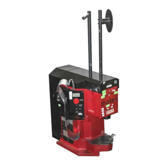
Page 1: Tm-2000 Universal Press
TM-2000 Universal Press TM-2000 UNIVERSAL PRESS Use with Molex FineAdjust or Mini-Mac Applicators Operation Manual Order No.63800-8399 Description Operation Maintenance UNCONTROLLED COPY Order No.: TM-638008399 Release Date: 08-08-02 Page 1 of 36 Revision: H Revision Date: 01-15-13... -
Page 2: Safety Warnings And Information
Keep this manual available when using this tool. Replacement manuals are available for download at no charge at www.molex.com. SAFETY ALERT SYMBOL This symbol is used to call your attention to hazards or unsafe practices which could result in an injury or property damage. - Page 3 Installation in crimp presses with other than standard shut heights can cause severe tool breakage. It is advisable that before installation, a check of the shut height be performed. Molex will not be liable for any damages as a result of installation in a crimp press with nonstandard or improperly set shut height.
-
Page 4: Table Of Contents
TM-2000 Universal Press Table of Contents Contents TM-2000 UNIVERSAL PRESS ............................. 1 Order No.63800-8399 ................................1 Safety Warnings and Information ............................2 Table of Contents ................................4 Section 1 ................................... 5 General Description ..............................6 Description................................. 6 Features ................................6 Technical Specifications ............................ -
Page 5: Section 1
TM-2000 Universal Press Section 1 General Description Description Features Technical Specifications Delivery Check Tools UNCONTROLLED COPY Order No.: TM-638008399 Release Date: 08-08-02 Page 5 of 36 Revision: H Revision Date: 01-15-13... -
Page 6: General Description
Flywheel Rotation: 210 RPM Description The 63800-8300 (120V AC version) and the 63800- Processing Capability 8400 (240V AC version) TM-2000 Universal Press is Up to 10 AWG (5.0mm²) of copper conductor in solid or an economical, electrically-operated, single-cycle stranded wire. -
Page 7: Section 2
TM-2000 Universal Press Section 2 Installation Lifting/Mounting Reel Support Foot Pedal and Power Connection Terminal Feed Guide Function Test Safety and Work Area Check UNCONTROLLED COPY Order No.: TM-638008399 Release Date: 08-08-02 Page 7 of 36 Revision: H Revision Date: 01-15-13... -
Page 8: Lifting/Mounting
Figure 2-1 ASSEMBLY WARNING: The TM-2000 Press weighs over 145 kg (320 lbs); it should not attempt to be lifted by one individual. Mechanical lifting devices should be used. A person lifting the press can sustain severe back or other injuries. -
Page 9: Foot Pedal And Power Connection
2.5 Function Test When the TM-2000 is shipped from the factory, it is set to the industry shut height of 135.80 mm (5.346”) with a calibrated load gauge. The press shut height gauge is spring loaded to give an accurate reading on the press shut height. See Figure 2-5. -
Page 10: Safety And Work Area Check
Observe where the emergency stop button is on the control panel. See Figure 2-6. Figure 2-6 CAUTION: Molex recommends that the operator and observers wear eye protection when the press is in operation or being serviced. UNCONTROLLED COPY Order No.: TM-638008399 Release Date: 08-08-02... -
Page 11: Section 3
TM-2000 Universal Press Section 3 Setup and Operation Applicator Installation and Removal Manually Cycling the Press Operation UNCONTROLLED COPY Order No.: TM-638008399 Release Date: 08-08-02 Page 11 of 36 Revision: H Revision Date: 01-15-13... -
Page 12: Applicator Installation And Removal
TM-2000 Universal Press 3.1 Applicator Installation and Removal Always turn off and disconnect the power supply to the press. Turn off the “POWER” switch located on the control panel. Steps 1. Remove press guard. 2. Verify that the applicator is for the product. (Reference specification sheets supplied with the applicator). -
Page 13: Operation
TM-2000 Universal Press 3. Always return the press back to top dead center insuring that the clutch collar is engaged by the actuator. This is done by reversing the direction of the 10mm wrench after hearing the clutch actuator make a click sound. -
Page 14: Section 4
TM-2000 Universal Press Section 4 Maintenance Clutch Service/Replacement Shim Installation/Removal Oiler UNCONTROLLED COPY Order No.: TM-638008399 Release Date: 08-08-02 Page 14 of 36 Revision: H Revision Date: 01-15-13... -
Page 15: Maintenance
COLLAR control panel. BACK SPRING HOUSING 1. Remove the rear cover of the TM-2000 press. Verify INPUT that the clutch control collar is in the locked position. See Figure 4-3. Insert the 10mm hex wrench into the socket head cap screw. This screw is located in the center of the flywheel. - Page 16 Removing the Clutch Unit WARNING: This procedure should be followed to ensure compliance with safety instructions. Molex cannot accept liability in the event of a subsequent accident caused by clutch failure when improperly serviced by the customer.
-
Page 17: Shim Installation/Removal
Always turn off and disconnect the power supply to the press. Turn off the “POWER” switch located on the control panel. The TM-2000 is shipped from the factory set at the industry shut height of 135.80mm ( 5.346”) . The shut height can be changed by adding or removing shims. SeeFigure 4-7. -
Page 18: Oiler
Feed a new wick up into the tube until it protrudes from the top end of the tube and replace the lid. Package of 25 Wicks: Molex Order No: 63890-0727 Figure 4-8 OILER ASSEMBLY Lubricant Oil... -
Page 19: Section 5
TM-2000 Universal Press Section 5 Parts List Assembly Drawings Electrical Schematics Troubleshooting UNCONTROLLED COPY Order No.: TM-638008399 Release Date: 08-08-02 Page 19 of 36 Revision: H Revision Date: 01-15-13... -
Page 20: Parts List
TM-2000 Universal Press Parts List 69018-7037 V – Belt 69018-7038 Pulley Item Order No. Description 69018-8135 Knurled Knob 63800-6905 Press Yoke 69018-8136 Quick Release Pin 63800-6997 Quick Change Mounting Plate 69018-8235 Hex Wrench (10 mm) 63800-8301 Press Frame 69018-9542 Compression Spring... -
Page 21: Assembly
TM-2000 Universal Press Assembly 1/4” TAPER GREASE FITTING M6 X 16LG SHCS (4) M6 X 25LG SHSS (2) M5 X 10LG BHCS (2) M6 X 20LG SHCS (2) M6 X 12LG BHCS M5 HEX NUT (2) M6 NUT W/ M6 WASHER... -
Page 22: Assembly (Continued)
TM-2000 Universal Press Assembly (continued) Figure 5-2 UNCONTROLLED COPY Order No.: TM-638008399 Release Date: 08-08-02 Page 22 of 36 Revision: H Revision Date: 01-15-13... -
Page 23: Assembly (Continued)
TM-2000 Universal Press Assembly (continued) 63800-8397: CONVERSION CABLE M6 X 12LG REQUIRED WHEN USING FOOTSWITCH 63800-8394 WITH CONTROL ASSEMBLY 63800-8390 M4 X 12LG SHCS (2) M5 X 10LG BHCS (2) M4 X 6LG BHCS (4) M6 X 10LG M5 WING NUT... -
Page 24: Assembly (Continued)
TM-2000 Universal Press Assembly (continued) M8 X 16LG BHCS (3) M4 X 12LG SHCS (2) M5 X 30LG SHCS M4 X 12LG SHCS (2) Figure 5-4 Quick Change Mounting Plate Assembly Item No. 2 (63800-6997) Item Order No. Description Required... -
Page 25: Electrical Schematic
TM-2000 Universal Press Electrical Schematic Figure 5-5 UNCONTROLLED COPY Order No.: TM-638008399 Release Date: 08-08-02 Page 25 of 36 Revision: H Revision Date: 01-15-13... -
Page 26: Electrical Parts List
TM-2000 Universal Press Electrical Parts List Item Order no Description Required 69002-5712 Control PCB Assembly 62500-0762 24 V Resettable Counter 69018-6251 Guard Open Red LED Assembly 69018-6223 E-Stop Button Assembly 69018-6222 Run Button Assembly 69018-6252 Run Green LED Assembly 69018-6226... -
Page 27: Troubleshooting
TM-2000 Universal Press Troubleshooting Symptom Cause Solution Power/Power cord failure Check supply Loose connection Refer to control schematic Guard interlock switch Install guard disengaged Motor will not run Fuse blown Replace On/Off switch failure Replace Motor thermal overload. Push reset button on motor Belt too tight Adjust Motor Mount. - Page 28 TM-2000 Universal Press For more information use the Quality Crimping Handbook There is no charge for this book, which can be found on the Molex Website (www.molex.com) or contact you local Molex sales engineer UNCONTROLLED COPY Order No.: TM-638008399 Release Date: 08-08-02...
- Page 29 TM-2000 Universal Press Appendix A Crimp Terminations Conductor Brush and Terminal Position Conductor Bell mouth and Terminal Cut-off Tab Conductor Crimp Height Measurement Insulation Crimp Pull Force Testing UNCONTROLLED COPY Order No.: TM-638008399 Release Date: 08-08-02 Page 29 of 36...
-
Page 30: Conductor Brush And Terminal Position
TM-2000 Universal Press TERMINAL ATTRIBUTES BEND UP ROLLING SEAM BELL CONDUCTOR BRUSH MOUTH CRIMP INSULATION CRIMP TWISTING STRIP LENGTH BEND DOWN CUT-OFF CRIMP HEIGHT A.1 Conductor Brush and Terminal Position Optimum Crimp Setup The insulation edge should be centered in the middle of the transition area. -
Page 31: Conductor Bell Mouth And Terminal Cutoff Tab
TM-2000 Universal Press Insulation Edge Centered in the Transition Area, Conductor Brush Too Long Cause: 1) Strip length too long. 2) Irregular wire cut-off or wire strands pulled from insulation bundle. Solution: 1) Verify strip length specification and adjust as necessary. -
Page 32: Crimp Height Measurement
TM-2000 Universal Press A-2.3 No or Small Bell mouth, Long Cutoff Tab Cause: 1) Terminal to tooling position. 2) Camber in the terminal strip. Solution: 1) Verify pull force. 2) Adjust terminal track towards operator Figure A-2.3 A-2.4 Excessive Bell mouth, Good Cutoff Tab Cause: 1) Check for worn conductor punch tooling. -
Page 33: Insulation Crimp
TM-2000 Universal Press ** It is normal for a termination to spring back to a final * Most common cause of crimp height variability crimp position after crimping. It is possible to achieve the same final crimp height with two different tool height A.4 Insulation Crimp... -
Page 34: Pull Force Testing
The pull is to be exerted by means of a tension testing machine or equivalent, so that there will be no sudden application of force or jerking during the test. The following is the procedure Molex uses for the qualification of pull force: 1. Cut wire length approximately 150mm (6.0”) long. - Page 35 TM-2000 Universal Press A.5.2 Pull Test Problems A.5.2.1 Wire breaks before conductor grip pull force low Test Values For Pullout Test UL486A Material Evaluation Conductor Size Pullout Force Cause: Wire material properties, and/or coatings. Solution: Test non-terminated wire for breaking strength.
- Page 36 Lisle, IL 60532 USA Date: Nov. 6 2000 Signed: ___________________________ Typed Name: Steven F. Wright Title: Director of Engineering Visit our Website at http://www.molex.com UNCONTROLLED COPY Order No.: TM-638008399 Release Date: 08-08-02 Page 36 of 36 Revision: H Revision Date: 01-15-13...
Need help?
Do you have a question about the TM-2000 and is the answer not in the manual?
Questions and answers