Table of Contents
Advertisement
Quick Links
Advertisement
Table of Contents
Troubleshooting

Related Manuals for Vollrath Stoelting U421 I2


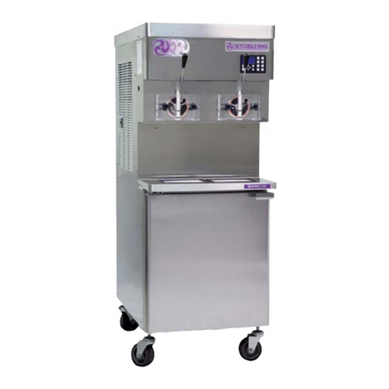
Summary of Contents for Vollrath Stoelting U421 I2
- Page 1 Model U421I2 OPERATORS MANUAL Manual No. 513685 Rev.0...
- Page 3 This manual provides basic information about the machine. Instructions and suggestions are given covering its operation and care. The illustrations and specifi cations are not binding in detail. We reserve the right to make changes to the machine without notice, and without incurring any obligation to modify or pro- vide new parts for machines built prior to date of change.
- Page 4 A Few Words About Safety Safety Information Safety Alert Symbol: Read and understand the entire manual before This symbol Indicates danger, warning or caution. operating or maintaining Stoelting equipment. Attention is required in order to avoid serious per- sonal injury. The message that follows the symbol This manual provides the operator with information contains important information about safety.
-
Page 5: Table Of Contents
TABLE OF CONTENTS Section Description Page Description and Specifi cations Description ....................1 Specifi cations ..................... 2 Installation Instructions Safety Precautions ..................3 Shipment and Transit .................. 3 Machine Installation ..................3 Installing Wiring ..................3 Mix Pump ....................4 Initial Startup of IntelliTec2™... - Page 6 Section Description Page Maintenance and Adjustments Overrun Adjustment ..................17 Mix Pump Hose Reposition ................ 17 Mix Pump Hose Replacement ..............18 Drive Belt Tension Adjustment ..............18 Condenser Cleaning (Air-Cooled Machines) ..........19 Preventative Maintenance ................19 Extended Storage ..................19 Troubleshooting Error Codes ....................
-
Page 7: Description And Specifications
SECTION 1 DESCRIPTION AND SPECIFICATIONS DESCRIPTION The Stoelting U421 I2 fl oor model machine is pressure fed. It is equipped with fully automatic controls to provide a uniform product. This manual is designed to assist qualifi ed service per- sonnel and operators with installation, operation and maintenance of the U421 I2. -
Page 8: Specifications
SPECIFICATIONS U421-I2 Water Cooled U421-I2 Air Cooled Dimensions Machine with crate Machine with crate width 26-3/4’’ (67,9 cm) 34’’ (86,4 cm) 26-3/4’’ (67,9 cm) 34’’ (86,4 cm) height 67-1/2’’ (171,5 cm) 78’’ (198,1 cm) 68-3/4’’ (174,6 cm) 78’’ (198,1 cm) depth 39-1/2’’... -
Page 9: Installation Instructions
SECTION 2 INSTALLATION INSTRUCTIONS 2.1 SAFETY PRECAUTIONS PRIOR TO INSTALLATION Locate a copy of the service contact fi le (info.txt). Do not attempt to operate the machine until the safety precautions and operating instructions in this manual are Modify the info.txt fi le with information from the read completely and are thoroughly understood. -
Page 10: Mix Pump
6” (15cm) Figure 2-2 Mix Hose Installation Remove the back panel and the junction box Feed one end of the mix pump hose into the cover located at the bottom of the machine. entering or pickup hose side (left) of black cover Install permanent wiring according to local code. - Page 11 Figure 2-3 Mix Pump Connections for Standard Mix Container Connect the free end of the mix pump hose to Connect 3/8” (9,5mm) ID plastic food grade tubing the 3-way Tee (Fig. 2-3). When all connections to a bag adapter. Secure with hose clamps. are complete, the 3-way Tee must be lower than Slide the hose clip over free end of 3/8”...
-
Page 12: Initial Startup Of Intellitec2
When Using Bag Connection System (BCS) with One 2.6 INTELLITEC2™ SETUP or Two Bags (optional kit #2183987): Disassemble, clean, lubricate and assemble the When connecting one or two bags, the manifold adapt- machine following the steps in Section 3. ers must be installed closest to the manifold outlet and Fill the mix containers in the cabinet with sanitizer. - Page 13 MOTOR CALIBRATION Before starting the motor calibration, be sure there is sanitizer in the freezing cylinder. Press the On/Off Left or On/Off Right button. The Motor Calibration screen will be displayed. Figure 2-7 The screen will change and show “File Found” for a quick second while it updates the information.
- Page 14 SETTING CONSISTENCY SETTING DISCHARGE PRESSURE ON WATER COOLED MACHINES Fill the mix container with liquid mix. Water cooled machines require the water Press the Pump On/Off button. Prime the freezing condenser valves to be adjusted to maintain a cylinder. After the pump button is pressed, mix will 235-240 psig discharge pressure.
-
Page 15: Initial Set-Up And Operation
SECTION 3 INITIAL SET-UP AND OPERATION 3.1 OPERATOR’S SAFETY PRECAUTIONS 3.2 OPERATING CONTROLS AND INDICATORS SAFE OPERATION IS NO ACCIDENT; observe these Before operating the machine, it is required that the op- rules: erator know the function of each operating control. Refer to Figure 3-1 for the location of the operating controls on Know the machine. -
Page 16: Disassembly Of Parts
A. INTELLITEC2™ TOUCHPAD Main Power On/Off The Main Power button is used to supply power to the IntelliTec2™ control, the freezing cylinder circuits and the storage refrigeration system. When the machine is fi rst plugged in, the control defaults to the On status with power to the cabinet only. -
Page 17: Cleaning Disassembled Parts
3.4 CLEANING DISASSEMBLED PARTS Disassembled parts require complete cleaning, sanitiz- ing and air drying before assembling. Local and state health codes will dictate the procedure required. Some state health codes require a four sink process (pre-wash, wash, rinse, sanitize, air dry), while others require a three sink process (without the pre-wash step). -
Page 18: Assembling The Machine
3.7 ASSEMBLING THE MACHINE To assemble the machine parts, refer to the following steps: NOTICE Petrol-Gel sanitary lubricant or equivalent must be used when lubrication of machine parts is specifi ed. NOTICE The United States Department of Agriculture and the Food and Drug Administration require that lubri- cants used on food processing equipment be certi- fi... -
Page 19: Sanitizing
When sanitizing the machine, refer to local sanitary regu- Press the CLEAN button to start the auger rotating. lations for applicable codes and recommended sanitizing Check for leaks when the freezing cylinder is fi rst products and procedures. The frequency of sanitizing pressurized with sanitizing solution. -
Page 20: Mix Information
When the product is ready, the display will read 3.11 OPERATION OF MIX PUMP “SERVE”. Open the spigot to dispense product. The mix pumps are operated from the buttons on the IntelliTec2™ touchpad. When the pump button is pressed NOTE On, the mix pump motor will start pumping mix into the If the product consistency needs to be adjusted, use freezing cylinder. -
Page 21: Mix Pump Cleaning
3.12 MIX PUMP CLEANING CAUTION NOTICE System Under Pressure Any cleaning procedure must always be followed by sanitizing before fi lling machine with mix. Never disconnect hoses from the machine or the pump without fi rst opening the spigot to relieve The mix pump is approved for CIP (clean in place). - Page 22 Owner’s Manual #513685 U421 I2 Model Machines...
-
Page 23: Maintenance And Adjustments
SECTION 4 MAINTENANCE AND ADJUSTMENTS This section is intended to provide maintenance personnel On the air compressor side of the pump, locate with a general understanding of the machine adjustments. the long/slender piston rocking arm. The rocking It is recommended that any adjustments in this section arm downward travel is limited by a stationery be made by a qualifi... -
Page 24: Mix Pump Hose Replacement
From the Current Status screen on the control Use a brush that fi ts in the opening and clean the press the left arrow button. pump roller assembly, fi rst with detergent water and then clear water. Press the right arrow, SET, then select button to get technician access to the control Connect the new mix pump hose to the pickup hose adapter using the small clamp. -
Page 25: Drive Belt Tension Adjustment
FINE CONSISTENCY ADJUSTMENT CONDENSER CLEANING (AIR-COOLED MACHINES) Product consistency can be adjusted on the Fine Consis- tency Adjustment screen. To get to the Fine Consistency The condenser requires periodic cleaning. To clean the Adjustment Screen, press the right arrow then the SEL condenser, refer to the following steps: button from the Current Status screen. - Page 26 Place the plastic auger fl ights in a plastic bag with a moist paper towel. This will prevent the fl ights from becoming brittle if exposed to dry air over an extended period (over 30 days). For water-cooled machines that are left in unheated buildings, or buildings subject to freezing, the water must be shut off and disconnected.
-
Page 27: Troubleshooting
SECTION 5 TROUBLESHOOTING 5.1 ERROR CODES Error Code 3 - Run Time The Run Time Error (E3) occurs when the When the machine experiences a problem, one of the compressor runs continuously for an extended following error codes will be displayed on the control period. - Page 28 Error Code 5 - Freezing Cylinder Sensor Error Code 10 - Auxiliary Sensor The Freezing Cylinder Sensor Error (E5) indicates An Auxiliary Temperature Sensor Error (E10) a failure of the barrel sensor or if the sensor is occurs if the temperature sensor on the control out of range.
-
Page 29: Troubleshooting - Machine
5.3 TROUBLESHOOTING - MACHINE PROBLEM POSSIBLE CAUSE REMEDY 1 Power to machine is off. 1 Supply power to machine. 2 Freeze-up (auger will not turn). 2 Turn off cylinder, wait for 15 minutes, then Machine does not restart. run. 3 Front door not in place. 3 Assemble front door in place. -
Page 30: Troubleshooting - Mix Pump
5.4 TROUBLESHOOTING - MIX PUMP PROBLEM POSSIBLE CAUSE REMEDY 1 Power to pump is off. 1 Supply power to pump. 2 Low voltage. 2 Check for low voltage. 3 Mix pump hose jammed inside black 3 Disconnect pump from power source. Remove cover/clamp. - Page 31 PROBLEM POSSIBLE CAUSE REMEDY 1 Mix pump hose service life is 1 Reposition/replace mix pump hose. exceeded. 2 Out of mix. 2 Replenish mix supply. Overrun too high. 3 Overrun setting too high. 3 Decrease overrun setting. 4 Pick-up leg of mix pump hose is 4 Reposition hose.
- Page 32 Owner’s Manual #513685 U421 I2 Model Machines...
-
Page 33: Replacement Parts
SECTION 6 REPLACEMENT PARTS BRUSHES, DECALS AND LUBRICATION Part Number Description Quantity 208135 Brush - 4” X 8” X 16” (Barrel) 208380 Brush - 1/4” X 3” X 14” 208387 Brush - 1/2” X 5” X 24” 208465 Brush - 1” X 3-1/2” X 18” 208467 Brush - 3/8”... -
Page 34: Auger Shaft And Front Door Parts
AUGER SHAFT AND FRONT DOOR PARTS 2183106 694200 624520 667868 381804 625133 694255 2187696 482004 1151859 482019 624598 624678 2204252 4151178 2104552 149003 Part Number Description Quantity 149003 Bushing - Front Auger Support 381804 Auger Flight 482004 Knob (Air Bleed Valve) 482019 Knob - Front Door (Black) 624520... -
Page 35: Cab Tubing
CAB TUBING Part Number Description Quantity 264235 Clamp - Metal (1/4” ID Tubing) (Cab) 264241 Clamp - Metal (1/2” ID Tubing) (Cab) 264243 Clamp - Metal (3/8” ID Tubing) (Cab) 376041 Tee Connector - 3-Way (Stainless) (Cab) 376097 Elbow - Barbed (1/2” x 1/4”) (Cab) 558109 Mix Container Only (Cab) 624607... - Page 36 Owner’s Manual #513685 U421 I2 Model Machines...
- Page 37 DOMESTIC WARRANTY (Including Mexico) SOFT SERVE / SHAKE EQUIPMENT 1. Scope: PW Stoelting, L.L.C. (“Stoelting”) warrants to the first user (the “Buyer”) that the freezing cylinders, hoppers, compressors, drive motors, speed reducers, and augers of Stoelting soft serve / shake equipment will be free from defects in materials and workmanship under normal use and proper maintenance appearing within five (5) years, and that all other components of such equipment manufactured by Stoelting will be free from defects in material and workmanship under normal use...
Need help?
Do you have a question about the Stoelting U421 I2 and is the answer not in the manual?
Questions and answers