
Subscribe to Our Youtube Channel
Related Manuals for Vollrath Stoelting E131-OT2


Summary of Contents for Vollrath Stoelting E131-OT2
- Page 1 https://appliancetechmanuals.com Model E131-OT2 / F131-OT2 SERVICE MANUAL Manual No. 513648 Rev.0...
- Page 2 https://appliancetechmanuals.com...
- Page 3 https://appliancetechmanuals.com This manual provides basic information about the machine. Instructions and suggestions are given covering its operation and care. The illustrations and specifi cations are not binding in detail. We reserve the right to make changes to the machine without notice, and without incurring any obligation to modify or pro- vide new parts for machines built prior to date of change.
- Page 4 https://appliancetechmanuals.com A Few Words About Safety Safety Information Safety Alert Symbol: Read and understand the entire manual before This symbol Indicates danger, warning or caution. operating or maintaining Stoelting equipment. Attention is required in order to avoid serious per- sonal injury. The message that follows the symbol This manual provides the operator with information contains important information about safety.
-
Page 5: Table Of Contents
https://appliancetechmanuals.com TABLE OF CONTENTS Section Description Page Description and Specifications Description ....................1 Specifications ..................... 1 Modes of Normal Operation ................ 4 Mix Level Indicators ..................6 Hopper Refrigeration ................... 6 Motor Profile Cutout Compensation ............6 Installation Instructions Safety Precautions ..................9 Shipment and Transit ................. - Page 6 https://appliancetechmanuals.com Section Description Page Refrigeration System Refrigeration System .................. 25 Refrigerant Recovery and Evacuation ............25 Refrigerant Charging ................... 26 Compressor ....................27 Condenser ....................28 Valves ......................28 Thermostatic Expansion Valve (TXV) ..............28 Check Valve ......................29 High Pressure Cutout ..................29 Hot Gas Bypass ....................
-
Page 7: Description
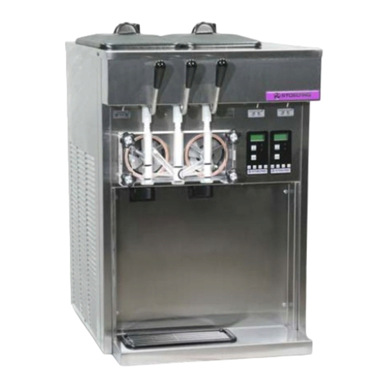
https://appliancetechmanuals.com SECTION 1 INTRODUCTION 1.1 DESCRIPTION The Stoelting E131OT2 and F131OT2 counter machines are gravity fed. The machines are equipped with fully automatic controls to provide a uniform product. They are designed to operate with almost any type of commercial soft serve or non-dairy mixes available, including: ice milk, ice cream, yogurt, and frozen dietary desserts. - Page 8 https://appliancetechmanuals.com E131I SPECIFICATIONS Model E131OT2 Dimensions Machine with crate 22'' (55,9 cm) 28'' (71,1 cm) width 34-3/4'' (88,3 cm) 40-1/4'' (102,2 cm) height 28-1/2'' (72,4 cm) 35-1/4'' (89,5 cm) depth 370 lbs (167,8 kg) 450 lbs (204,1 kg) Weight Electrical 1 Phase, 208-230 VAC, 60Hz approximately 12A running amps...
- Page 9 https://appliancetechmanuals.com F131I SPECIFICATIONS Model F131OT2 Dimensions Machine with crate 22'' (55,9 cm) 28'' (71,1 cm) width 34-3/4'' (88,3 cm) 40-1/4'' (102,2 cm) height 28-1/2'' (72,4 cm) 35-1/4'' (89,5 cm) depth 385 lbs (174,6 kg) 470 lbs (213,1 kg) Weight Electrical 1 Phase, 208-230 VAC, 60Hz approximately 12A running amps...
-
Page 10: Modes Of Normal Operation
https://appliancetechmanuals.com 1.3 MODES OF NORMAL OPERATION Following are details of the operational modes of the IntelliTec control. NOTE: The preset amounts, times, and temperatures listed below are references to actual settings on the IntelliTec control. Refer to Table 1-1 on page 7 for details on each setting. - Page 11 https://appliancetechmanuals.com the "Sleep 1 Mode". Refer to Figure 1-4 for a graphical representation of the "Standby Mode". If a spigot is opened or the PUSH TO FREEZE button is pressed, the control will move to “Serve Mode”. Product in the front of the freezing cylinders may or may not be at consistency.
-
Page 12: Mix Level Indicators
https://appliancetechmanuals.com audible alarm is a reminder for the operator to end the control will run the machine on timers for the freezing cycle "Clean Mode" when cleaning is completed. or hopper refrigeration. This allows the operator to continue to serve product from the machine until proper servicing can If the machine is kept in "Clean Mode"... - Page 13 https://appliancetechmanuals.com IntellITec Control Setting Specifications Basic Menu DISPLAY E131 & F131 MODE DEFINITION CutOut Serve Amp draw setting for cut out 22°F Cut In T Serve Temperature setting for cut in Cycles Serve Freezing cycles before going into Standby Mode 15 sec Stir On Serve...
- Page 14 https://appliancetechmanuals.com...
-
Page 15: Installation Instructions
https://appliancetechmanuals.com SECTION 2 INSTALLATION INSTRUCTIONS 2.1 SAFETY PRECAUTIONS Do not attempt to operate the machine until the safety precautions and operating instructions in this manual are read completely and are thoroughly understood. Take notice of all warning labels on the machine. The labels have been put there to help maintain a safe working environment. - Page 16 https://appliancetechmanuals.com...
-
Page 17: Initial Set-Up And Operation
https://appliancetechmanuals.com SECTION 3 INITIAL SET-UP AND OPERATION 3.1 OPERATOR’S SAFETY PRECAUTIONS 3.2 OPERATING CONTROLS AND INDICATORS SAFE OPERATION IS NO ACCIDENT; observe these rules: Before operating the machine, it is required that the operator know the function of each operating control. Refer Know the machine. - Page 18 https://appliancetechmanuals.com Push to Freeze A. MAIN FREEZER POWER SWITCH The Main Freezer Power switch is a two position rocker Green LED switch that supplies power to the IntelliTec control, freez- ing cylinder circuits and hopper refrigeration system. When Amber LED the switch is placed in the ON position, the hopper refrig- eration system will run until the preset temperature is Clean Button...
-
Page 19: Important Information Regarding Cleaning And Sanitizing
https://appliancetechmanuals.com SANITIZING 3.3 IMPORTANT INFORMATION REGARDING CLEANING AND SANITIZING · Kills bacteria. Soft serve machines require special consideration when it · Can be effective on clean surfaces only. comes to food safety and proper cleaning and sanitizing. NOTE The following information specifically covers issues for Using a SANITIZER on an unclean surface will not cleaning and sanitizing frozen dessert machines. -
Page 20: Disassembly Of Machine Parts
https://appliancetechmanuals.com MACHINE DAMAGE – Strong acids will attack Inspection for worn or broken parts should be made at every metal and rubber causing premature wear of disassembly of the machine. All worn or broken parts parts. The use of a delimer needs to be closely should be replaced to ensure safety to both the operator and monitored to avoid damage to machine surfaces the customer and to maintain good machine performance... -
Page 21: Cleaning Disassembled Parts
https://appliancetechmanuals.com B. DISASSEMBLY OF AUGER Remove the front auger support and bushing. Remove the auger assembly from the machine. Pull the auger out of the machine barrel slowly. As the auger is being pulled out, carefully remove each of the plastic flights with springs. Keep the rear of the auger tipped up once it is clear of the freezing cylinder to prevent the rear seal assembly from dropping. -
Page 22: Assembling The Machine
https://appliancetechmanuals.com Apply a thin layer of sanitary lubricant to the inside 3.8 ASSEMBLING MACHINE and outside of the auger support bushing. Install To assemble the machine parts, refer to the following steps: the bushing onto the auger support and install the NOTICE auger support into the front of the auger. -
Page 23: Initial Freeze Down And Operation
https://appliancetechmanuals.com Place the Main Power OFF/ON and Freezing Change the value to 8.0. Press the left arrow (⇐) Cylinder OFF/ON switches in the ON position. button to move the cursor. Press the up arrow (⇑) Press the CLEAN button. button to increase the digit. When a digit reaches 9, pressing the up arrow (⇑) button again will Check for leaks. -
Page 24: Normal Freeze Down And Operation
https://appliancetechmanuals.com Press the SEL button three times. The LCD will When the product is at 75% consistency, the read “EXITMENU”. display will read “SERVE”. Open the spigot to dispense product. Press the up arrow (⇑) button to exit the menu. The machine dispenses product at a reasonable Adjustment to the control is completed. -
Page 25: Maintenance And Adjustments
https://appliancetechmanuals.com SECTION 4 MAINTENANCE AND ADJUSTMENTS MACHINE ADJUSTMENT LOCKING THE CONTROL PANEL This section is intended to provide maintenance person- The IntelliTec control has a tamper proof mode to prevent nel with a general understanding of the machine adjust- unauthorized use. When set, all buttons on the control ments. - Page 26 https://appliancetechmanuals.com...
-
Page 27: Readings
https://appliancetechmanuals.com Modifying Control Settings Aux. Temp (°F) To change the value of a system function, locate the This reading provides the ambient temperature function on the IntelliTec Settings Menu and follow the around the IntelliTec control. steps below. Supply V (VAC) IMPORTANT: A calculated input voltage is recorded. -
Page 28: Adjustments
https://appliancetechmanuals.com Up Time (hours) Cut In T (°F) This value is a record of the total time the machine After the consistency value has been determined, has been in service. If power is interrupted, the the Cut In T value can be adjusted. The Cut In T timer will stop until power is restored. -
Page 29: Drive Belt Tension Adjustment
https://appliancetechmanuals.com Off Time (sec) DRIVE BELT TENSION ADJUSTMENT Increasing this value will increase the time between To check belt tension, refer to Figure 4-4 and follow the freezing cycles in "Standby Mode" and result in an steps below: increase of product temperature in the barrel. Stb Time (sec) WARNING This setting determines the total amount of time in... -
Page 30: Preventative Maintenance
https://appliancetechmanuals.com on the right and left sides of the unit for free flow of air. Make 4.10 PREVENTATIVE MAINTENANCE sure the machine is not pulling over 100° F (37° C) air from It is recommended that a preventative maintenance sched- other equipment in the area. -
Page 31: Refrigeration System
https://appliancetechmanuals.com SECTION 5 REFRIGERATION SYSTEM 5.1 REFRIGERATION SYSTEM NOTE The E131OT2 and F131OT2 refrigeration systems have two For qualified service personnel only. Anybody work- functions: ing with refrigerants must be certified as a Techni- cian TYPE I as required by 40 CFR 82 Subpart F Medium-Temperature - Maintaining mix temperature and hold all State and/or local refrigerant handling in the hopper. -
Page 32: Refrigerant Charging
https://appliancetechmanuals.com A. REFRIGERANT RECOVERY B. EVACUATING THE REFRIGERATION SYSTEM Disconnect the machine from electrical supply Close any open ports in the refrigeration system. before removing any panels for servicing. Connect a vacuum gauge to one of the Schrader Remove all panels. valves next to an evaporator. -
Page 33: Compressor
https://appliancetechmanuals.com Remove the front panel. WARNING Remove the protective cover from the compressor terminals. Disconnect the three terminals; C Hazardous voltage (common), R (run), and S (start). The Main Freezer Power switch must be placed in Connect an ohmmeter to the C and R terminals on the OFF position when disassembling for servicing. -
Page 34: Condenser
https://appliancetechmanuals.com C. COMPRESSOR INSTALLATION 5.6 VALVES Make sure the machine is disconnected from the A. AUTOMATIC EXPANSION VALVE (AXV) electrical supply before removing any panels for The Automatic Expansion Valve (AXV) is used to meter the servicing. refrigerant to the freezing cylinder evaporator. It does so by Install the four rubber mounts on the compressor. -
Page 35: Check Valve
https://appliancetechmanuals.com Replace insulation to the AXV and surrounding NOTE lines. The AXV is the LAST component to adjust in the Replace the drier per the instructions in Section refrigeration system. 5.9. The AXV can be adjusted after the steps above are completed. -
Page 36: Hot Gas Bypass
https://appliancetechmanuals.com HIGH PRESSURE CUTOUT REPLACEMENT NOTE With the suction and discharge ports open, braze If the machine does not have a Main Power switch, the capillary tube to the discharge line. turn the right side Freezing Cylinder switch OFF and listen to make sure the left freezing cylinder is not Replace the drier per the instructions in Section calling for refrigeration. -
Page 37: Evaporator Pressure Regulator (Epr)
https://appliancetechmanuals.com HOT GAS BYPASS REPLACEMENT EPR REMOVAL To replace the hot gas bypass, perform the following Remove the left side panel and front panel. procedures: Recover refrigerant charge per instructions in Apply a heat sink (wet cloth) to the hot gas bypass. Section 5.2. -
Page 38: Solenoid
https://appliancetechmanuals.com WATER VALVE REMOVAL The water valve is connected to the refrigeration system by capillary tube brazed to the discharge line. Turn off and disconnect the water supply. Blow out the water lines with compressed air or CO Recover refrigerant charge per instructions in Section 5.2. - Page 39 https://appliancetechmanuals.com may have a leaking valve seat. SUCTION LINE SOLENOID TESTING To check for leaking valve seats, follow the procedure SOLENOID MAGNETIC COIL REMOVAL outlined below. The liquid line solenoid must remain open Remove the side panel. for this test. Disconnect the electrical wires.
-
Page 40: Filter Drier
https://appliancetechmanuals.com 5.8 FILTER DRIER 5.9 CAPILLARY TUBE The filter drier must be replaced every time the refrigeration The capillary tube meters refrigerant flow in the mix line system is opened for service. A new filter drier improves evaporator (Refer to Figure 5-14). The amount of flow is operation of the entire refrigeration system by stopping the dependent on the length and ID of the capillary tube as well circulation of moisture and by removing harmful contami-... -
Page 41: Electrical And Mechanical Control Systems
https://appliancetechmanuals.com SECTION 6 ELECTRICAL AND MECHANICAL CONTROL SYSTEMS NOTE The wiring diagram is available in Section 8. INTELLITEC CONTROLLER Understanding the modes of operation and individual con- trol settings will make servicing the control straightforward. COMPONENTS OF CONTROLLER The IntelliTec control consists of three main components; the control board (Figure 6-1), the membrane switch (Figure 6-2), and the display panel module (Figure 6-3). -
Page 42: Drive Motor
https://appliancetechmanuals.com Place the Main Power OFF/ON and Freezing A. CONTACTOR TESTS Cylinder OFF/ON switches in the OFF position. The following tests will show if a contactor is working properly. Install the belt and tighten the tension bolt. Open right side panel and visually check the Use a Burroughs Belt Tension Gauge to set the IntelliTec control board. -
Page 43: Capacitors
https://appliancetechmanuals.com Test for proper belt tension by pressing firmly on A. CAPACITOR TEST the belt. When the tension is properly adjusted, the Disconnect machine from electrical supply before belt should depress approximately 3/8” (roughly removing any panels for servicing. the width of the belt). Using a straightedge, align the drive motor pulley with the gearbox pulley. -
Page 44: Gearbox
https://appliancetechmanuals.com B. CAPACITOR REPLACEMENT CONDENSER FAN MOTOR (AIR- COOLED ONLY) Disconnect machine from electrical supply before removing any panels for servicing. A. FAN MOTOR REPLACEMENT Place the Main Power OFF/ON switch and both Disconnect machine from electrical supply before Freezing Cylinder OFF/ON switches in the OFF removing any panels for servicing. -
Page 45: Spigot Switch
https://appliancetechmanuals.com SPIGOT SWITCH SPIGOT SWITCH TESTING - ELECTRICAL Disconnect the switch from the circuit by unplugging The spigot switch is a normally closed, held open switch. the connectors. When a spigot is pulled, the spigot switch sends a signal to the IntelliTec control to start the auger drive and refrigera- tion system. -
Page 46: Temperature Control Sensor
https://appliancetechmanuals.com Remove the two Phillips head screws that attach the spigot cam assembly to the panel. Remove the assembly. Disconnect the connector from the switch and remove the switch.. Install the replacement switch onto the handle assembly. Do not fully tighten the retaining screws at this time. -
Page 47: Troubleshooting
https://appliancetechmanuals.com SECTION 7 TROUBLESHOOTING from a restriction preventing mix from entering the 7.1 ERROR CODES freezing cylinder. Check the mix in the hopper. If When the machine experiences a problem, one of the the level mix is low, add mix. If there is a possibility following error codes will be displayed on the control panel. - Page 48 https://appliancetechmanuals.com Error Code 5 - Freezing Cylinder Sensor Error Code 8 - Cab Sensor The Freezing Cylinder Sensor Error (E5) indicates A Cab Sensor Error (E8) will not occur on the a failure of the barrel sensor or an extreme out of machine.
-
Page 49: Servicing Tip
https://appliancetechmanuals.com the resistance of the sensor, place a thermocouple The display panel lights will also flash in an alternating on the suction line at the exit of the freezing sequence under any error codes. Clear the error cylinder. Compare temperature and sensor and place the Freezing Cylinder Off-On switch in resistance with the table as reference. -
Page 50: Troubleshooting - Machine
https://appliancetechmanuals.com 7.4 TROUBLESHOOTING - MACHINE PROBLEM POSSIBLE CAUSE REMEDY 1. Power to machine is off. 1. Supply power to machine. 2. Blown fuse or tripped circuit. 2. Replace or reset. 3. Freeze-up (auger will not turn). 3. Turn CLEAN-OFF-ON switch to OFF (middle) Machine does not position for 15 minutes, then restart. -
Page 51: Replacement Parts
https://appliancetechmanuals.com SECTION 8 REPLACEMENT PARTS 8.1 DECALS AND LUBRICATION Part Description Quantity 208135 Brush - 4" X 8" X 16" (Barrel) 208380 Brush - 1/4" X 3" X 14" 208401 Brush - 1" X 3" X 10" 208467 Brush - 3/8" X 1" X 5" 236025 Card - Cleaning Instruction 324065... -
Page 52: Auger Shaft And Faceplate Parts
https://appliancetechmanuals.com 8.2 AUGER SHAFT AND FACEPLATE PARTS... - Page 53 https://appliancetechmanuals.com 8.2 AUGER SHAFT AND FACEPLATE PARTS (CONTINUED) Part Description Quantity 149003 Bushing - Front Auger Support 232734 Cap - Rosette - Teardrop 266076 Clip - Drip Tray 314453 Cover - Hopper 381804 Auger Flight 6 (E131) 8 (F131) 417006 Grid - Drip Tray (Metal) 482019 Knob - Front Door (Black)
-
Page 54: Machine Front
https://appliancetechmanuals.com 8.3 FRONT 428045 2187805 718532 718532 482004 719025-SV Part Description Quantity 215061 Plug - Bumber (Drip Tray) 428045 Knob - Spigot Handle (Black) 482004 Knob (Spigot Adjustment) 718532 Switch - Toggle (Freezing Cylinder & Main Power On-Off) 719025-SV Switch - Membrane Strip 1158090-SV Switch - Door Interlock 2183006... -
Page 55: Left Side
https://appliancetechmanuals.com 8.5 LEFT SIDE 246048 2171962 E131 - 4183213 F131 - 4183218 272065 Coil 763423 Valve 763482 Coil 763017 763422 Valve Part Description Quantity 246048 Spacer - Speed Reducer 2 (E131) 272065 Valve Coil - Solenoid (#763723 Valve) 458003 Indicator - Liquid Line 763017 Valve - Hot Gas Bypass 763422... -
Page 56: Right Side
https://appliancetechmanuals.com 8.6 RIGHT SIDE 229116 765214 295017 744142 521686-230 295005 618157 E131 - 230633 E131 - 230632 F131 - 231084 F131 - 231079 8.7 FRONT 762978 VA-0070 342004 E131 - 282045 F131 - 282032 342020 E131 - 439171 231107... - Page 57 https://appliancetechmanuals.com 8.6 RIGHT SIDE (CONTINUED) Part Description Quantity 229116 Cable - Phone (Control Board To Display Board) 230632 Capacitor - Start (#282045 Compressor) 1 (E131) 230633 Capacitor - Run (#282045 & #282050 Compressors) 230649 Capacitor - Start (#282050 Compressor) 1 (F131) 231027 Capacitor - Run (#282052 Compressor) 1 (E131)
-
Page 58: Rear
https://appliancetechmanuals.com 8.8 REAR 614233 598245 E131 - 284071 F131 - 284084 762275 522291 152323 162077 598072 522858-SV 430119... - Page 59 https://appliancetechmanuals.com 8.8 REAR (CONTINUED) Part Description Quantity 152323 Belt - Grip-Notch (AX-39) (Each) 162077 Blade - Fan (Air-Cooled Condenser) 231096 Capacitor - Run (Motor) 231095 Capacitor - Start (Motor) 284071 Condenser (Air-Cooled) 1 (E131) 284084 Condenser (Air-Cooled) 1 (F131) 284104 Condenser (Water-Cooled) 368140 Filter - Air (Condenser)
-
Page 60: Refrigeration Diagram & Wiring Diagram
https://appliancetechmanuals.com 8.9 REFRIGERATION DIAGRAM & WIRING DIAGRAM... - Page 61 https://appliancetechmanuals.com...
Need help?
Do you have a question about the Stoelting E131-OT2 and is the answer not in the manual?
Questions and answers