Table of Contents
Advertisement
Quick Links
www.ti.com
User's Guide
Using the UCC27624EVM
This user's guide describes the characteristics, operation, and use of the UCC27624EVM Evaluation Module
(EVM). A complete schematic diagram, PCB layouts, and BOM are included in this document.
1
Introduction.............................................................................................................................................................................2
2 Description..............................................................................................................................................................................
2.1 Features.............................................................................................................................................................................
2.2 I/O Description...................................................................................................................................................................
3 Electrical Specifications........................................................................................................................................................
4 Test Summary.........................................................................................................................................................................
4.1 Definitions..........................................................................................................................................................................
4.2 Equipment..........................................................................................................................................................................
Setup................................................................................................................................................................4
5.1 Power Up...........................................................................................................................................................................
Down.......................................................................................................................................................................6
Delays............................................................................................................................................................7
7
Schematic................................................................................................................................................................................8
Diagrams.....................................................................................................................................................................9
Materials.....................................................................................................................................................................13
Figure 7-1. UCC27624EVM Schematic.......................................................................................................................................
Figure 8-1. Top Overlay...............................................................................................................................................................
Layer...................................................................................................................................................................9
Figure 8-3. Bottom Layer...........................................................................................................................................................
Overlay........................................................................................................................................................10
Figure 8-5. Top Image................................................................................................................................................................
Figure 8-6. Bottom Image..........................................................................................................................................................
Table 2-1. Connection Descriptions.............................................................................................................................................
Settings..................................................................................................................................................5
Table 9-1. UCC27624EVM List of Materials..............................................................................................................................
SLUUCE4 - JUNE 2021
Submit Document Feedback
ABSTRACT
Table of Contents
Procedure.................................................................................................................................6
= 1800 pF).................................................................................................................
List of Figures
Configuration..................................................................................................................5
Waveforms......................................................................................................................6
..............................................................................................................7
List of Tables
Settings.................................................................................................................4
Copyright © 2021 Texas Instruments Incorporated
Table of Contents
2
2
3
3
4
4
4
6
7
8
9
10
11
12
3
13
Using the UCC27624EVM
1
Advertisement
Table of Contents

Related Manuals for Texas Instruments UCC27624EVM


Summary of Contents for Texas Instruments UCC27624EVM
-
Page 1: Table Of Contents
Table of Contents User’s Guide Using the UCC27624EVM ABSTRACT This user's guide describes the characteristics, operation, and use of the UCC27624EVM Evaluation Module (EVM). A complete schematic diagram, PCB layouts, and BOM are included in this document. Table of Contents Introduction.....................................2 2 Description.................................... -
Page 2: Introduction
5-A peak source and 5-A peak sink current for driving Si/IGBTs/SiC and GaN FETs. The UCC27624EVM board can be used to evaluate other pin-to-pin compatible parts in the supported package. The UCC27624 has low propagation delay and low propagation delay matching between the respective channels rising and falling edges of the driver outputs for reliable timing of the gate-drive signals. -
Page 3: I/O Description
UCC27624 Datasheet UCC27624 30-V, 5-A dual channel low-side driver Data Sheet. CAUTION The UCC27624EVM is designed for low-voltage evaluation only, and is not certified for evaluation with voltages beyond the absolute maximums listed in the electrical specifications. Do not evaluate high-voltage parameters with this board. -
Page 4: Test Summary
Test Summary www.ti.com 4 Test Summary 4.1 Definitions This procedure details how to configure the UCC27624EVM evaluation board. Within this test procedure, the following naming conventions are applied. See the UCC27624EVM Bench Setup Diagram and Configuration, Figure 4-1, for details. -
Page 5: Figure 4-1. Bench Setup Diagram And Configuration
Connect oscilloscope Ch-2 probes to test points marked as Gate_B, smaller measurement loop is preferred; see in Figure 4-1. Figure 4-1. Bench Setup Diagram and Configuration SLUUCE4 – JUNE 2021 Using the UCC27624EVM Submit Document Feedback Copyright © 2021 Texas Instruments Incorporated... -
Page 6: Power Up And Power Down Procedure
5.2 Power Down Use the following steps to power down the EVM: 1. Disable function generator 2. Disable power supply #1 3. Disconnect cables and probes Using the UCC27624EVM SLUUCE4 – JUNE 2021 Submit Document Feedback Copyright © 2021 Texas Instruments Incorporated... -
Page 7: Typical Performance Waveforms (C L = 1800 Pf)
To evaluate propagation delays and rising and falling details, it is recommended to have scope probe connections with short ground leads. Figure 6-1. IN+ to OUT Propagation Delay Waveforms SLUUCE4 – JUNE 2021 Using the UCC27624EVM Submit Document Feedback Copyright © 2021 Texas Instruments Incorporated... -
Page 8: Schematic
Schematic www.ti.com 7 Schematic Figure 7-1 shows the UCC27624EVM schematic diagram. OUTA 12V 50mA Gate_A OUTA Gate_A OUTA 0.1uF 47uF 10.0k OUTB U1_OUT_Conn 220nF_Load_A 10k _Load_A Ω OUTB 10.0k 220nF 1.8nF INA_INB_Conn OUTB TP10 UCC27624D INA_IN Gate_B Gate_B 49.9 TP13 10pF 10.0k... -
Page 9: Layout Diagrams
Layout Diagrams 8 Layout Diagrams Figure 8-1 through Figure 8-6 show the PCB layout information for the UCC27624EVM. Figure 8-1. Top Overlay Figure 8-2. Top Layer SLUUCE4 – JUNE 2021 Using the UCC27624EVM Submit Document Feedback Copyright © 2021 Texas Instruments Incorporated... -
Page 10: Figure 8-3. Bottom Layer
Layout Diagrams www.ti.com Figure 8-3. Bottom Layer Figure 8-4. Bottom Overlay Using the UCC27624EVM SLUUCE4 – JUNE 2021 Submit Document Feedback Copyright © 2021 Texas Instruments Incorporated... -
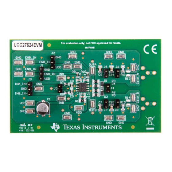
Page 11: Figure 8-5. Top Image
Layout Diagrams Figure 8-5. Top Image SLUUCE4 – JUNE 2021 Using the UCC27624EVM Submit Document Feedback Copyright © 2021 Texas Instruments Incorporated... -
Page 12: Figure 8-6. Bottom Image
Layout Diagrams www.ti.com Figure 8-6. Bottom Image Using the UCC27624EVM SLUUCE4 – JUNE 2021 Submit Document Feedback Copyright © 2021 Texas Instruments Incorporated... -
Page 13: List Of Materials
List of Materials 9 List of Materials Table 9-1. UCC27624EVM List of Materials QUANTITY DESCRIPTION DESCRIPTION CAP, AL, 47 uF, 50 V, +/- 20%, 0.68 ohm, SMD C2, C12 CAP, CERM, 1 uF, 50 V, +/- 10%, X6S, 0603 C3, C13 CAP, CERM, 0.1 uF, 50 V, +/- 10%, X7R, 0402... - Page 14 List of Materials www.ti.com Table 9-1. UCC27624EVM List of Materials (continued) UCC27624 Dual, 5A, High-Speed Low-Side Power MOSFET Driver, with Negative Input Voltage Ability, D0008A (SOIC-8) Using the UCC27624EVM SLUUCE4 – JUNE 2021 Submit Document Feedback Copyright © 2021 Texas Instruments Incorporated...
- Page 15 STANDARD TERMS FOR EVALUATION MODULES Delivery: TI delivers TI evaluation boards, kits, or modules, including any accompanying demonstration software, components, and/or documentation which may be provided together or separately (collectively, an “EVM” or “EVMs”) to the User (“User”) in accordance with the terms set forth herein.
- Page 16 www.ti.com Regulatory Notices: 3.1 United States 3.1.1 Notice applicable to EVMs not FCC-Approved: FCC NOTICE: This kit is designed to allow product developers to evaluate electronic components, circuitry, or software associated with the kit to determine whether to incorporate such items in a finished product and software developers to write software applications for use with the end product.
- Page 17 www.ti.com Concernant les EVMs avec antennes détachables Conformément à la réglementation d'Industrie Canada, le présent émetteur radio peut fonctionner avec une antenne d'un type et d'un gain maximal (ou inférieur) approuvé pour l'émetteur par Industrie Canada. Dans le but de réduire les risques de brouillage radioélectrique à...
- Page 18 www.ti.com EVM Use Restrictions and Warnings: 4.1 EVMS ARE NOT FOR USE IN FUNCTIONAL SAFETY AND/OR SAFETY CRITICAL EVALUATIONS, INCLUDING BUT NOT LIMITED TO EVALUATIONS OF LIFE SUPPORT APPLICATIONS. 4.2 User must read and apply the user guide and other available documentation provided by TI regarding the EVM prior to handling or using the EVM, including without limitation any warning or restriction notices.
- Page 19 Notwithstanding the foregoing, any judgment may be enforced in any United States or foreign court, and TI may seek injunctive relief in any United States or foreign court. Mailing Address: Texas Instruments, Post Office Box 655303, Dallas, Texas 75265 Copyright © 2019, Texas Instruments Incorporated...
- Page 20 TI products. TI’s provision of these resources does not expand or otherwise alter TI’s applicable warranties or warranty disclaimers for TI products.IMPORTANT NOTICE Mailing Address: Texas Instruments, Post Office Box 655303, Dallas, Texas 75265 Copyright © 2021, Texas Instruments Incorporated...
Need help?
Do you have a question about the UCC27624EVM and is the answer not in the manual?
Questions and answers