Table of Contents
Advertisement
Quick Links
Advertisement
Table of Contents

Related Manuals for WEST PAM-190-P Series

Summary of Contents for WEST PAM-190-P Series
- Page 1 Technical Documentation PAM-190-P Amplifier plug for proportional valves...
-
Page 2: Table Of Contents
CONTENTS General Information ..............................3 Order number ..............................3 Scope of supply .............................. 3 Accessories ..............................3 Symbols used ..............................4 Legal notice ..............................4 Safety instructions ............................5 Characteristics ................................. 6 Device description ............................7 Use and application ..............................8 Installation instructions ........................... -
Page 3: General Information
1 General Information 1.1 Order number - Power amplifier for proportional valves with 0… 10 V input and M12 connector PAM-190-P-A - Power amplifier for proportional valves with 4… 20 mA input and M12 connector PAM-190-P-I Alternative products PAM-190-P-IO - Amplifier plug for proportional valves with IO-Link interface - Mobile amplifier in IP65 housing with 0…... -
Page 4: Symbols Used
1.4 Symbols used General information Safety-related information 1.5 Legal notice W.E.St. Elektronik GmbH Gewerbering 31 D-41372 Niederkrüchten Tel.: +49 (0)2163 577355-0 Fax.: +49 (0)2163 577355-11 Home page: www.w-e-st.de EMAIL: contact@w-e-st.de Date: 05.06.2020 The data and characteristics described herein serve only to describe the product. The user is required to evaluate this data and to check suitability for the particular application. -
Page 5: Safety Instructions
1.6 Safety instructions Please read this document and the safety instructions carefully. This document will help to define the product area of application and to put it into operation. Additional documents (WPC-300 for the start-up software) and knowledge of the application should be taken into account or be available. General regulations and laws (depending on the country: e. -
Page 6: Characteristics
2 Characteristics This amplifier plug is used to control proportional valves with one solenoid. The compact and inexpensive so- lution will be mounted directly on the solenoid. A typical input signal of 0… 10 V (optional 4... 20 mA) can be used. The output current is closed loop con- trolled and therefore independent from the supply voltage and a varying solenoid resistance. -
Page 7: Device Description
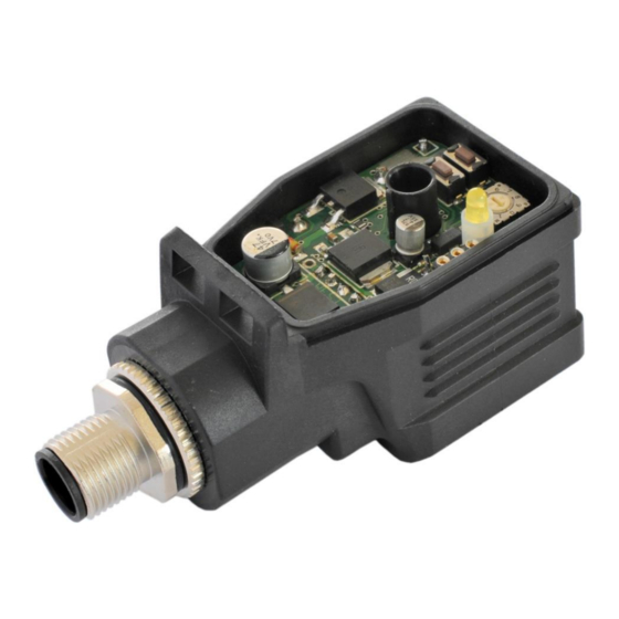
2.1 Device description M12-Plug (5pol) Operation LED Parameter LED IEC 61076-2-101 Funktions LED Parameter LED (M12-Version) Selection Switch Dreh- schalter Button Down Taste Ab Button Up Taste Auf Pin layout M12/5 plug Type-label Typenschild Rectangle Plug / Rechteck Verbinder Type: A EN 175301-803 Rubber-seal / Dichtung Page 7 of 24 PAM-190-P-A/I... -
Page 8: Use And Application
3 Use and application 3.1 Installation instructions All cables which lead outside must be screened; complete screening is required. It is also a require- ment that no strong electro-magnetic interference sources are installed nearby when using our control and regulation modules. ... -
Page 9: Commissioning
3.2 Commissioning Step Task Installation Install the device in accordance with the circuit diagram. Ensure it is wired cor- rectly and that the signals are well shielded. Ensure that no unwanted movement is possible in the drive (e. g. switch off the Switching on for the first time hydraulics). -
Page 10: Manual Parameterization
3.3 Manual parameterization 3.3.1 Parameter overview The manual adjustment is comparable with the adjustment via potentiometer. Not all parameters of the power plug are available in this mode Switch Parameter Setting range Remark position DEFAULT Released only by pressing the button "Up" and "DOWN" simultaneously. -
Page 11: Technical Description
4 Technical description 4.1 Input and output signals Connection Supply PIN 1 Power supply (see technical data) PIN 3 0 V (GND) connection. Connection Analogue signals (Differential) Command signal input +, signal range 0… 10 V or 4… 20 mA, scalable PIN 2 (Differential) Command signal input -, signal range 0…... -
Page 12: Circuit Diagram
4.3 Circuit diagram PAM-190-P Power- supply Input Valve Power Input / Ramp Adaptation Stage Scaling Generator To the solenoid Differential input PE via DIN-PLUG Communication LIN Bus Control program Page 12 of 24 PAM-190-P-A/I 05.06.2020... -
Page 13: Typical Wiring
4.4 Typical wiring Valve / Ventil ULA-310 Link to the PLC Verbindung zur SPS USB-Plug-Socket to PC USB-Buchse zum PC 4.5 Connection examples SPS / PLC 0... 10 V 4... 20 mA input +In PIN 2 +In PIN 2 -In PIN 4 -In PIN 4 GND PIN 3 AIN:W 1000 1000... -
Page 14: Technical Data
4.6 Technical data 12… 30 (incl. ripple) [VDC] Supply voltage [mA] Current requirement < 50 + solenoid current External protection 3 medium time lag Analog inputs: 0… 10 Voltage [kOhm] Input resistance min. 90 Siganl resolution 0.026 4… 20 Current [mA] [Ohm] Shunt... -
Page 15: Parameters
5 Parameters 5.1 Parameter overview Group Command Default Unit Description Basic parameters Changing language help texts MODE Parameter view Input signal adaptation Signal scaling AIN:W 1000 Free scaling of the analogue input. 1000 0,01 % Range monitoring 0,01 % Signal monitoring function (e.g. joystick error) Ramp function R:UP Command signal ramp times... -
Page 16: Basic Parameters
5.2 Basic parameters 5.2.1 LG (Changing the language) Command Parameters Unit Group x= DE|EN Either German or English can be selected for the help texts. CAUTION: After changing the language settings the parameter list has to be updated by pressing the identification button “ID”. -
Page 17: Insignal Adaptation
5.3 Input signal adaptation 5.3.1 AIN (Analogue input scaling) Command Parameters Unit Group AIN:W a= -10000… 10000 b= -10000… 10000 c= -10000… 10000 0,01 % x= V|C This command offers an individual scalable input. The following linear equation is used for the scaling. “C”... -
Page 18: Lim (Signal Monitoring)
5.3.2 LIM (Signal monitoring) Command Parameters Unit Group x= 0… 2000 0,01 % This command defines the pressure, which corresponds to 100 % of the input signal. If the demand is set incorrectly, this leads to incorrect system settings, and the dependent parameters cannot be calculated correctly. -
Page 19: Output Signal Adaptation
5.4 Output signal adaptation 5.4.1 MIN (Deadband compensation) 5.4.2 MAX (Output scaling) 5.4.3 TRIGGER (Response threshold for the MIN parameter) Command Parameters Unit Group x= 0… 6000 0,01 % x= 2000… 10000 0,01 % TRIGGER x= 0… 3000 0,01 % With this command, the output signal is adjusted to the valve characteristics. -
Page 20: Pol (Output Polarity)
5.4.4 POL (Output polarity) Command Parameter Unit Group + | - This command allows a switch over of the output signal direction (after the MIN-MAX function). Input signal 0… 100 %, nominal output current 0… 100 %. Example: POL:A Input signal 0… 100 % nominal output current 100… 0 %. POL:A 5.5 Output signal adaptation 5.5.1... -
Page 21: Pwm (Pwm Frequency)
5.5.4 PWM (PWM Frequency) Command Parameter Unit Group x= 60… 2650 This parameter is entered in Hz. The optimum frequency depends on the valve. CAUTION: when using low PWM frequencies the PPWM and PPWM parameters should be adjusted The PWM frequency can only be set in defined steps. This means that there are deviations between the specified and the actual frequency. -
Page 22: Process Data (Monitoring)
5.6 PROCESS DATA (Monitoring) Command Description Unit Command value after input scaling Comman value after ramp function Control signal Solenoid current The process data are the variables which can be observed continuously on the monitor or on the oscilloscope. The display of the solenoid current (in WPC-300 program) is damped in order to be able to bring out a stable signal. Page 22 of 24 PAM-190-P-A/I 05.06.2020... -
Page 23: Appendix
6 Appendix 6.1 Failure monitoring Following possible error sources are monitored continuously: Source Fault Characteristic Command signal PIN 2 / 4 Out of range The output will be switched off and the READY LED flashes. LIM command Command signal PIN 2 / 4 Out of range or broken wire The output will be switched off and the READY LED flashes. -
Page 24: Notes
7 Notes Page 24 of 24 PAM-190-P-A/I 05.06.2020...
Need help?
Do you have a question about the PAM-190-P Series and is the answer not in the manual?
Questions and answers