Table of Contents
Advertisement
Quick Links
Advertisement
Table of Contents

Related Manuals for Teledyne Lecroy WavePulser 40iX


Summary of Contents for Teledyne Lecroy WavePulser 40iX
- Page 1 WavePulser 40iX High-speed Interconnect Analyzer Getting Started Guide...
- Page 2 Teledyne LeCroy documentation for internal educational purposes only. WavePulser and Teledyne LeCroy are trademarks of Teledyne LeCroy, Inc. Other product or brand names are trademarks or requested trademarks of their respective holders. Information in this publication supersedes all earlier versions.
-
Page 3: Table Of Contents
Welcome Thank you for buying a Teledyne LeCroy product. We’re certain you’ll be pleased with the detailed features unique to our instruments. This guide is intended to help you set up a WavePulser and learn some basic operating procedures, so you're quickly making measurements. -
Page 4: Introduction
Introducing WavePulser Key Specifications Detailed specifications are on the product datasheet at teledynelecroy.com. WavePulser 40iX is the ideal single measurement tool for high-speed Number of Ports hardware designers and test engineers. The combination of S-parameters (frequency domain) and Impedance Profiles (time domain) in a single Connector Type 2.92 mm K... -
Page 5: Wavepulser Approach
INTRODUCTION WavePulser Approach Pulser/ Pulser/ Pulser/ Pulser/ Sampler Sampler Sampler Sampler WavePulser uses time domain reflectometry to characterize a DUT’s elec- trical behavior by stimulating the DUT with impulses and measuring reflec- tion and transmission. Once a measurement is configured, all phases Internal Calibration Reference Plane proceed without any user intervention whatsoever. -
Page 6: Set Up
SET UP Safety Power and Ground AC Power 100-240 VAC (±10%) at 50/60/400 Hz (±5%) To maintain the instrument in a correct and safe condition, observe gener- Automatic AC Voltage Selection ally accepted safety practices in addition to the precautions specified here. Consumption Maximum Operating 40 W / 40 VA... - Page 7 Shield Calibration The recommended factory calibration interval is one year. Calibration should be performed by qualified personnel only. See p.33 for instructions on returning the instrument to Teledyne LeCroy Service. WavePulser Getting Started Guide...
-
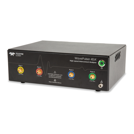
Page 8: Wavepulser Hardware
SET UP WavePulser Hardware Front View Rear View A. Power On/Standby Power Button D. USBTMC Port B. Port 1 - Port 4 Connectors E. AC Power Inlet C. Ground Terminal 933197-00 Rev A... - Page 9 SET UP Cables SI Kit (Optional) The WavePulser ships with high-phase stability cables that are calibrated The SI Kit is delivered with the WavePulser-40iX-Bundle or may be and serialized to the WavePulser unit, along with the S-parameter files for purchased as an optional accessory. This option enables the Signal Integrity de-embedding each cable.
-
Page 10: System Set Up
SET UP System Set Up Install WavePulser Software 1. Visit teledynelecroy.com/support/softwaredownload and click the The WavePulser system consists of the WavePulser unit, cables and link to WavePulser Downloads > WavePulser Software. application host computer. 2. Enter the required model information and account login to download the installer for your operating system. - Page 11 2. Open the Instrument Setup dialog and select Run SelfTest. by users. 3. If you are alerted to any errors, click SelfTest Log and review the findings. \Waveforms stores .TRC files of saved waveform data. If necessary, contact Teledyne LeCroy Customer Support to resolve errors. WavePulser Getting Started Guide...
-
Page 12: Connecting Cables
SET UP Connecting Cables Proper Handling of Cables • Always use the supplied grounding wrist strap when handling cables to avoid ESD damage. • Discharge cables before connecting them to the WavePulser or DUT. • Use the proper adapter when connecting cables to DUTs, or when connecting other than the supplied cables to the WavePulser. - Page 13 SET UP Confirming Cable De-embedding Connecting to DUT During installation, .S2P files for de-embedding the cables are transferred Attach the free ends of the cables to the DUT, using adapters if required. from the WavePulser SD card to the host application. To confirm that the Take care to not rotate the connector head, only turn the nut to tighten.
-
Page 14: Basics
BASICS WavePulser Application Window The WavePulser application user interface contains these prinicpal elements: A. Menu Bar B. Action Buttons C. Grid D. Cursors E. Level Indicators F. Time/Frequency Indicators G. Trace Descriptor Boxes H. Setup Dialogs 933197-00 Rev A... - Page 15 BASICS A drop-down menu bar lets you access set up dialogs and other functions. Trace descriptor boxes appear along the bottom of the grid, one for each open trace. They adjust in size and detail as more are opened. See If an action can be “undone”...
-
Page 16: Basic Configuration
BASICS Basic Configuration The Setup dialog contains all the basic settings required for making any type of meaurement. See the WavePulser User Manual for detailed instructions on using these settings. Choose Setup from the menu bar to open the dialog. Set Up Acquisition As you modify the End Freq and Num Points, you'll notice the values for Delta Freq and Time Length change. - Page 17 BASICS Configure Ports If you've connected single-ended inputs to the same number port on the WavePulser as on the DUT (1 to 1, 2 to 2, etc.), and none of the ports have been skipped, you need only enter the Num(ber of) Ports in use. If you wish to calculate mixed-mode S-parameters or change any port assignments, click + to expand, then check Enable and click Configure.
-
Page 18: Advanced Configuration
BASICS Advanced Configuration The following settings are optional. If your test setup calls for them, click the + button to expand the Setup dialog. You can apply these settings following acquisition, then just Recalculate the results. See the WavePulser User Manual for more information on using these features. Physicality If you wish to used saved calibration data or are using the external Cal Kit, click the Calibration button and set up Manual calibration. -
Page 19: Viewing Tdr/Tdt Waveforms
BASICS Viewing TDR/TDT Waveforms Raw, uncalibrated TDR/TDT waveforms can be acquired and displayed as either an impulse response or step response for a crude impedance profile. Because they respond quickly to manipulation of the DUT, TDR/TDT traces are also useful for checking signal integrity at different points on the circuit. Turn Pulse On for each port to which to send the pulse, then turn Trace On for each port from which you wish to view the response. -
Page 20: Viewing Frequency Domain Results
BASICS Viewing Frequency Domain Results Using the measurements calculated from the calibrated TDR/TDT waveforms, the WavePulser application generates Result traces (Sn), which plot a single S-parameter measurement. Result traces can be analyzed with standard tools such as Cursors, Measure and Math, or used as inputs to SI Studio. Go to WavePulser Setup >... -
Page 21: Viewing Time Domain Results
BASICS Viewing Time Domain Results Time domain results are displayed using the same procedure as for frequency domain results. Optionally, click the Config button to smooth the trace by increasing rise time or applying SinX/X upsampling, or to change the x-axis units from Time to Distance. Time results Impedance Profile, Step Response, Impulse Response, and Rho. -
Page 22: Viewing The Smith Chart
BASICS Viewing the Smith Chart You can display an Admittance Smith Chart of any two calculated or imported S-parameters simply by selecting them from the Smith Chart dialog. Optionally, modify the chart by changing the frequency range plotted (the full range of the last measurement is the default), or display Result traces alongside the Smith Chart by changing the Smith Chart Display selection. -
Page 23: Calculating Loss (Delta-L)
Calculating Loss (Delta-L) The Delta-L feature applies the Intel Delta-L loss characterization method to calculate loss (in dB) per unit length of a PCB trace without calibrating at the ® end of probe tips. It can be calculated from a new acquisition or saved S-parameters. Simply enter the electrical lengthof the DUT and the frequencies at which to calculate. -
Page 24: Importing S-Parameters
BASICS Importing S-Parameters You can import external S-parameters on the SParam Import dialog and view the S-parameters as different Result traces, only in this case, the traces are labeled Rn on the display. Browse to and select the Touchstone file, then follow the same procedure as for displaying internal results (p.18-19). Import files should be in Touchstone 1.1 format, the same in which the WavePulser saves files. -
Page 25: Exporting S-Parameters
BASICS Exporting S-Parameters The Touchstone files are saved in the Magnitude and Frequency Format selected on the SParam Export dialog. The default format is Magnitude/Angle in MHz. You can also use this dialog to save the latest calculated S-parameters on demand. Saving/Recalling Other Data Waveforms, Setups and Table Data The current WavePulser configuration can be saved to internal setup... -
Page 26: Working With Result Traces
BASICS Working With Result Traces Trace Descriptor Boxes Descriptor boxes appear along the bottom of the grid area when a trace is turned on, summarizing the current settings of the traces they represent. They are color-coded to the trace. Clicking the descriptor box is a shortcut to the rescale dialog for that trace. - Page 27 BASICS Zooming Traces Zooming allows you to "zoom in" on waveform details or "zoom out" to see a greater span of acquisition. There are two principal ways to zoom a trace. Rectangle Zoom New Zoom Trace Click-and-drag diagonally to draw a rectangle around the part of the Zoom traces (Zn) display a magnified portion of another trace.
-
Page 28: Changing The Display
BASICS Changing the Display Cursors To modify the WavePulser application display, choose Display > Display Cursors set measurement points on the Vertical or Horizontal axis of Setup from the menu bar and make your selections from the Display dialog. a trace. Not only can you choose the type of cursor to apply, you can choose which set of values are displayed for each cursor position. -
Page 29: Measurements And Statistics
BASICS Measurements and Statistics Math Measurements are waveform parameters that can be expressed as Math creates a new Function (Fn trace) that displays the result of numerical values, such as amplitude or frequency. You can measure applying a mathematical operation (e.g., Sum, Product, FFT) to one or up-to-eight parameters on various traces and view the active readout in more source traces. -
Page 30: Memories (Reference Waveforms)
BASICS Memories (Reference Waveforms) Pass/Fail Testing Pass/Fail testing enables you to define a set of queries (rules) comparing a Memories are traces stored for reference that can be individually recalled to the display (unlike a saved measurement, which restores all traces). To trace to mask a region, or comparing a measurement to an arbitrary limit or second measurement, and immediately see whether it "passed"... -
Page 31: Using Si Studio With Wavepulser
Once activated, the SI Studio menu is enabled on the WavePulser menu bar. Note: If you do not see these selections, you may need to add a software license key to activate SI Studio. Contact your Teledyne LeCroy represen- tative for instructions. - Page 32 BASICS Eye Doctor II Channel Emulator/Equalizer Eye Doctor II is a complete set of signal integrity tools performing the full-range of de-embedding, emulation and equalization, with little impact on waveform processing time. Results are fully integrated with the other SI Studio tools, making Signal Generator signals available for Eye Doctor processing, and Eye Doctor outputs available for further analysis using the deep SDA toolbox.
- Page 33 BASICS Serial Data Analysis Software (SDA) Serial Data Analysis software provides comprehensive measurement capabilities for evaluating high-speed serial data signals. Signal Integrity Studio includes the full suite of SDA II single-lane eye and jitter analysis capabilites. Click blocks to define input signal and clock recovery (or explicit ref clock), then add all desired Eye and Jitter measurements.
-
Page 34: Maintenance
Software Updates Clean the outside of the WavePulser using a soft cloth moistened Free updates are available periodically from the Teledyne LeCroy website with water or isopropyl alcohol solution. Do not use harsh or abrasive at teledynelecroy.com/support/softwaredownload. Registered users will cleansers. -
Page 35: Service
All products returned to the factory must have an RMA. Service Centers For a complete list of Teledyne LeCroy offices by country, including our Return shipments must be prepaid. Teledyne LeCroy cannot accept COD sales and distribution partners, visit: teledynelecroy.com/support/contact or Collect shipments. -
Page 36: Support
LECROY WILL RETURN ALL PRODUCTS UNDER WARRANTY WITH TRANSPORT out of your Teledyne LeCroy products. The user manual can also be PREPAID. downloaded from the Technical Library under Manuals. -
Page 37: Reference
REFERENCE Touchstone File Format Operational Notes S-parameter files saved by the WavePulser are in Touchstone 1.1 format. Using Other Cables To use other S-parameter files with WavePulser or SI Studio software: If you use any other than the supplied cables, you must: •... -
Page 38: Certifications
Certifications 2 Emissions which exceed the levels required by this standard may occur when the instrument is Teledyne LeCroy certifies compliance to the following standards as of connected to a test object. the time of publication. Please see the EC Declaration of Conformity 3 This product is intended for use in nonresidential areas only. - Page 39 EN 61010-2:030:2010 Safety requirements for electrical equipment electronic equipment in standard waste receptacles. For more information for measurement, control, and laboratory use – Part 2-030: Particular about proper disposal and recycling of your Teledyne LeCroy product, requirements for testing and measuring circuits please visit teledynelecroy.com/recycle.
- Page 40 933197-00 Rev A, April, 2021 © 2021 Teledyne LeCroy, Inc. All rights reserved.
Need help?
Do you have a question about the WavePulser 40iX and is the answer not in the manual?
Questions and answers