Table of Contents
Advertisement
Quick Links
Advertisement
Table of Contents

Related Manuals for Teledyne Lecroy HDA125


Summary of Contents for Teledyne Lecroy HDA125
- Page 1 Operator's Manual HDA125 High-speed Digital Analyzer...
- Page 3 HDA125 High-speed Digital Analyzer Operator's Manual August, 2016...
- Page 4 HDA125, WaveSurfer, WaveRunner, WavePro, WaveMaster, LabMaster, and Teledyne LeCroy are trademarks of Teledyne LeCroy, Inc. Other product or brand names are trademarks or requested trademarks of their respective holders. Information in this publication supersedes all earlier versions. Specifications are subject to change without notice.
-
Page 5: Table Of Contents
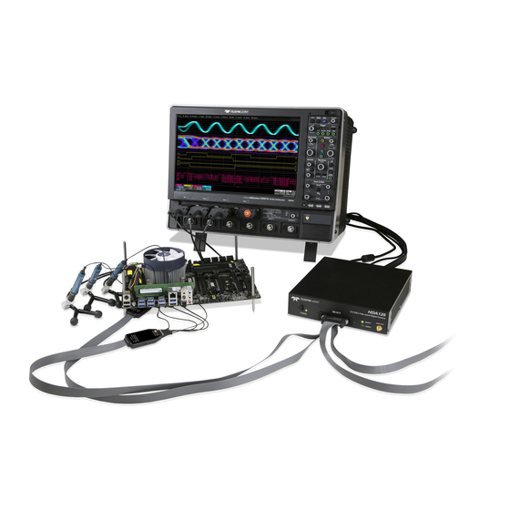
Handling the Digital Leadset ................... 6 Order of Operations ......................6 Connecting the Digital Leadset ..................7 Connecting HDA125 to the Oscilloscope ................ 8 Connecting QL-SI Tips to the Digital Leadset ............... 10 Connecting QL-SI Tips to the QuickLink Adapter ............11 Deskewing ........................ - Page 6 The HDA125 is a powerful solution for the challenge of measuring multiple, mixed signals in a single oscilloscope. An accessory for the Teledyne LeCroy Zi series oscilloscopes, the HDA125 extends their testing range by adding 9 or 18 digital channels for waveform display or triggering.
-
Page 7: Introduction
QuickLink probing system. The HDA125 is ideally suited for embedded system testing where there is a proliferation of analog signals coincident with digital signals. You can easily debug signals using standard oscilloscope tools such as cursors, measurement parameters, and zooming. -
Page 8: Safety
HDA125 High-speed Digital Analyzer Safety Observe these instructions to keep the product operating in a correct and safe condition. Follow generally accepted safety procedures in addition to the precautions specified here. The overall safety of any system incorporating this product is the responsibility of the assembler of the system. - Page 9 Operator’s Manual grounded mating outlet. Connect and disconnect properly. Do not connect/disconnect probes or test leads while they are connected to a live voltage source. Exercise electrostatic discharge (ESD) precautions. The digital leadsets and probe tips are sensitive to ESD. When making connections to the device under test, always wear a grounding wrist strap.
-
Page 10: Technical Overview
HDA125 High-speed Digital Analyzer Technical Overview The HDA125 is an external device that digitally samples waveform data at up to 12.5 GS/s (enabling acquisition of digital signals up to 6 Gb/s). Unlike a logic analyzer, it operates only in a Timing Analysis mode, so it requires oversampling to determine the correct digital edge position, and does not require the user to input a clock. -
Page 11: Hda125 Set Up
Operator’s Manual HDA125 Set Up Standard Parts The HDA125 is delivered as either a 9-channel kit or an 18-channel kit with the following hardware. HDA125-18- HDA125-09- HDA125-18- HDA125-09- Parts LBUS LBUS SYNC SYNC HDA125 High-speed Digital Analyzer HDA-DLS-18QL 18-channel Digital Leadset... -
Page 12: Handling The Digital Leadset
(wear wrist strap, etc.) when using or handling the equipment. Order of Operations To ensure that all components (HDA125 and leadset) are correctly identified by the system software, the following order of operations is recommended: 1. Close the oscilloscope application, or shut down the oscilloscope. -
Page 13: Connecting The Digital Leadset
Operator’s Manual Connecting the Digital Leadset Connect the digital leadset to the digital input on the front of the HDA125. Push the connector until it “snaps” into place. When removing the leadset, press the tabs on both sides of the connector head, then pull out. -
Page 14: Connecting Hda125 To The Oscilloscope
Connecting HDA125 to the Oscilloscope Oscilloscopes with an LBUS Interface Connect the LBUS cable from the LBUS connector on the back of the HDA125 to the LBUS connector on the back of the oscilloscope. Be sure the head is turned so that the wedge fits into the groove at the top of the connector. - Page 15 Operator’s Manual Oscilloscopes with a ChannelSync Interface The ChannelSync interface is used to connect the HDA125 to LabMaster systems. NOTE: In systems based on the LabMaster Master Control Module, be sure to connect at least one Acquisition Module to the MCM Zi (as described in the LabMaster Operator’s Manual) before connecting the HDA125.
-
Page 16: Connecting Ql-Si Tips To The Digital Leadset
HDA125 High-speed Digital Analyzer Connecting QL-SI Tips to the Digital Leadset Solder the QL-SI tips to the device under test, then insert the connector head of the tip into the leadset pod, matching the tip color to the port color. -
Page 17: Connecting Ql-Si Tips To The Quicklink Adapter
Any QL-SI tip can be connected to a WaveLink™ Low-bandwidth or Medium- bandwidth Modular Differential Probe using the QuickLink™ Adapter (sold separately from the HDA125) in order to view the signal as an analog waveform. There is no need to remove the tip from the device under test; just remove the QL-SI connector head from the digital leadset pod and insert it into the QuickLink Adapter. -
Page 18: Deskewing
HDA125 High-speed Digital Analyzer Deskewing Before using the HDA125, it is crucial to deskew the signal path to ensure proper signal timing. Since the HDA125 is typically used in embedded applications, it is assumed that it will be used in conjunction with differential analog probes capturing signals on the oscilloscope’s analog channels. - Page 19 SMA cable can be used to terminate the PCF200 to one of the oscilloscope’s outputs. 5. Connect the QL-SI tip to one of the empty slots in the HDA125 connector pods. 6. Go to Vertical > Digital1 Setup and create the Digital1 group with only the line that you connected to the PCF200.
- Page 20 10. Touch the Digital1 descriptor box to open the Digital1 dialog, then touch Store to save the FastEdge trace to memory. 11. Disconnect the HDA125 connector pod from the PCF200 adapter, and connect the first probe to be deskewed.
- Page 21 Operator’s Manual 12. Touch the Cx descriptor box to open the channel dialog and adjust the channel’s Deskew value so that the 50% rising edge point matches the rising edge stored in memory, as shown below: 13. Now, decrease the timebase to around 20 ps/div and adjust the Deskew value so that the 50% rising edge point is centered in time.
-
Page 22: Digital Setup
Skew The Skew setting is useful in cases where the HDA125 is being used to acquire several signals that are time-aligned, but the QL-SI tips have been soldered to the bus in a “staggered” fashion, thus introducing skew between the signals. -
Page 23: Digital Group Setup
Operator’s Manual Digital Group Setup This procedure organizes the digital lines into groups, which correspond to buses. Lines generally correspond to the physical QL-SI tips, although any tip can be assigned to any line number (and color) to make it easier to assemble groups without having to disconnect tips from the test device. -
Page 24: Renaming Digital Lines
HDA125 High-speed Digital Analyzer Renaming Digital Lines You can give each line a user-defined name to make the interface more intuitive. Touch the Dx button immediately below the Dx selection checkbox (the words "Change Line Name" appear at the far left of the row). Use the virtual keyboard that appears on the touch screen to enter a new name. - Page 25 Operator’s Manual Change Trace Style You can also change the Display Mode setting to view a digital Bus trace that collapses all the lines in a group into their Hex values, or both Lines and Bus. The size and placement of the lines depend on the number of lines, and the Vertical Position and Line Height settings.
-
Page 26: Digital Triggering
HDA125 High-speed Digital Analyzer Digital Triggering Accessing the Trigger Dialogs To access the Trigger setup dialogs, do one of the following: Touch the Trigger descriptor box • Press the front panel Trigger Setup button • Choose Trigger > Trigger Setup from the menu bar •... -
Page 27: Pattern Trigger
Operator’s Manual Pattern Trigger Digital Pattern is the default trigger when the HDA125 is connected to the oscilloscope. However, a Pattern trigger can also be set on a user-defined pattern of High or Low voltage levels on analog channels (including the External Trigger input), or a combination of digital and analog patterns. - Page 28 HDA125 High-speed Digital Analyzer Digital Pattern Using Logic If you have not set up digital groups, you can set a digital pattern line by line using the Logic method. All available lines remain active for selection. At the far right of the Digital Pattern dialog, choose Logic.
-
Page 29: Maintenance
Calibration Your HDA125 hardware does not need periodic calibration. However, we do recommend that the oscilloscope used with the HDA125 be returned for annual factory calibration. See Returning a Product for Service. Firmware Updates Teledyne LeCroy offers state-of-the-art performance by continually improving our oscilloscope capabilities. -
Page 30: Technical Support
HDA125 High-speed Digital Analyzer Technical Support Phone Registered users can contact their local Teledyne LeCroy service center at the number listed in this manual to make Technical Support requests by phone or email. You can also submit Technical Support requests via the website at: teledynelecroy.com/support/techhelp... -
Page 31: Returning A Product For Service
Operator’s Manual Returning a Product for Service Contact your local Teledyne LeCroy service center for calibration or other service. If the product cannot be serviced on location, the service center will give you a Return Material Authorization (RMA) code and instruct you where to ship the product. -
Page 32: Certifications
HDA125 High-speed Digital Analyzer Certifications Teledyne LeCroy certifies compliance to the following standards as of the time of publication. For the most current certifications, please see the EC Declaration of Conformity certificate shipped with your product. EMC Compliance EC DECLARATION OF CONFORMITY - EMC The product meets the intent of EC Directive 2014/30/EU for Electromagnetic Compatibility. - Page 33 Operator’s Manual European Contact:* Teledyne LeCroy Europe GmbH Im Breitspiel 11c D-69126 Heidelberg Germany Tel: (49) 6221 82700 AUSTRALIA & NEW ZEALAND DECLARATION OF CONFORMITY—EMC The product complies with the EMC provision of the Radio Communications Act per the following standards, in accordance with requirements imposed by Australian Communication and Media Authority: AS/NZS CISPR 11:2011 Radiated and Conducted Emissions, Group 1, Class A.
- Page 34 The product is subject to disposal and recycling regulations that vary by country and region. Many countries prohibit the disposal of waste electronic equipment in standard waste receptacles. For more information about proper disposal and recycling of your Teledyne LeCroy product, please visit teledynelecroy.com/recycle. RESTRICTION OF HAZARDOUS SUBSTANCES (ROHS)
-
Page 35: Warranty
WARRANTY WITH TRANSPORT PREPAID. The product is warranted for normal use and operation, within specifications, for a period of three years from shipment. Teledyne LeCroy will either repair or, at our option, replace any product returned to one of our authorized service centers within this period. -
Page 36: Contact Us
HDA125 High-speed Digital Analyzer Contact Us For a complete list of offices by country, including our sales & distribution partners, visit: teledynelecroy.com/support/contact Teledyne LeCroy 700 Chestnut Ridge Road Chestnut Ridge, NY, 10977, USA teledynelecroy.com Sales and Service: Ph: 800-553-2769 / 845-425-2000 FAX: 845-578-5985 contact.corp@teledynelecroy.com... -
Page 37: Notes
Operator’s Manual Notes... - Page 38 HDA125 High-speed Digital Analyzer...
- Page 40 927294-00 Rev A August, 2016...
Need help?
Do you have a question about the HDA125 and is the answer not in the manual?
Questions and answers