
Subscribe to Our Youtube Channel
Related Manuals for SystemAir SYSAER R32 SR R32 105


Summary of Contents for SystemAir SYSAER R32 SR R32 105
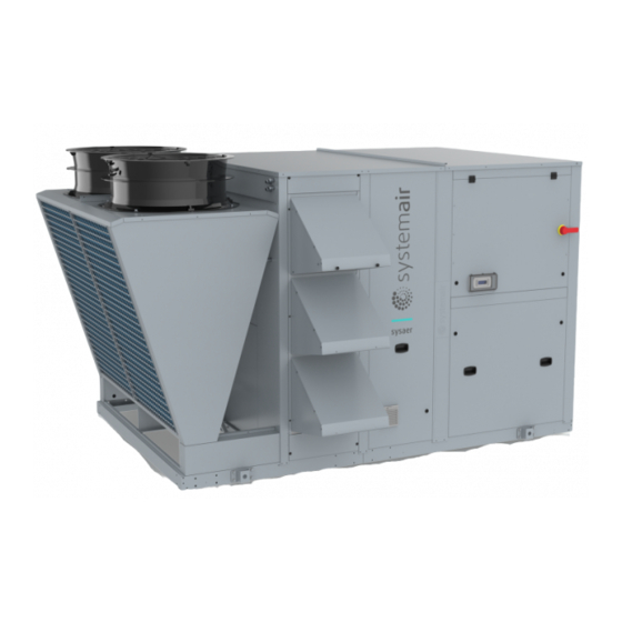
- Page 1 Installation and maintenance manual SYSAER R32 SR R32 105 / SR R32 140 Roof-mounted air conditioning unit 106 â 139 kW 106 â 142 kW 19 200 â 25 500m...
- Page 3 INSTALLATION INSTRUCTION English NOTICE D’INSTALLATION Français INSTALLATIONSHANDBUCH Deutsch ISTRUZIONI INSTALLAZIONE Italiano INSTRUCCIONES DE INSTALACIÓN Español...
-
Page 4: Table Of Contents
2 SYSAER R32 CONTENTS 1. GENERAL RECOMMENDATIONS ................................ 3 1.1. SAFETY DIRECTIONS ............................................3 1.2. INFORMATION ON THE REFRIGERANT USED ....................................3 1.3. INSTALLATION INFORMATION ........................................4 1.3.1. GENERAL GUIDELINES FOR SAFE USE OF R32 FOR EQUIPMENT LOCATED IN THE OPEN AIR ........................4 1.3.2. -
Page 5: General Recommendations
SYSAER R32 POWER SUPPLY MUST BE SWITCHED OFF BEFORE STARTING WORK IN THE ELECTRIC CONTROL BOX 1. GENERAL RECOMMENDATIONS The purpose of this Manual is to provide users with instructions for installing, commissioning, using and maintaining the units. It does not contain the complete description of all the maintenance operations guaranteeing the unit’s long life and reliability. -
Page 6: Installation Information
4 SYSAER R32 Safety class (ISO 817) PED Group Practical limit (kg/m 0.061 ATEL/ ODL (kg/m 0.30 LFL (kg/m ) @ 60°C 0.307 Vapour density @25°C, 101.3 kPa (kg/m 2.13 Molecular mass 52.0 Boiling point (°C) GWP (100 yr ITH) GWP (ARS 100 yr ITH) Autoignition temperature (°C) 1.3. - Page 7 SYSAER R32 Machinery rooms shall have doors opening outward and sufficient in number to ensure persons can escape in an emergency. The doors shall be tight fitting and self-closing. They shall be so designed that they can be ² opened from inside (anti-panic system). The doors shall have at least a one-hour fire resistance construction, using materials and construction tested in accordance with EN 1634.
-
Page 8: Gas Detector
6 SYSAER R32 Refrigerant detectors for R32 ² A refrigerant detector for a group A2L refrigerant shall activate the alarm signal at a level not exceeding 25 % of the LFL of the refrigerant. The detector shall continue to activate at higher concentrations. -
Page 9: Equipment Safety Data
SYSAER R32 1.6. EQUIPMENT SAFETY DATA Safety Data Difluoromethane R32 Chemical Formula CH2F2 Toxicity Classification of substance Flammable gas – Category 1 – Danger (H220) Gases under pressure – Liquefied gas – Warning (H280) Critical temperature (°C) -78,4 °C @ 58,10 Bar Upper/lower flammability 28,40 Vol. - Page 10 8 SYSAER R32 Safety Data Difluoromethane R32 Protect containers from physical damage; do not drag, roll, slide or drop. Do not remove or deface labels provided by the supplier for the identification of the container contents. When moving containers, even for short distances, use appropriate equipment eg. trolley, hand truck, fork truck etc.
-
Page 11: Inspection And Storage
SYSAER R32 2. INSPECTION AND STORAGE At the time of receiving the equipment carefully cross check all the elements against the shipping documents in order to ensure that all the crates and boxes have been received. Inspect all the units for any visible or hidden damage. -
Page 12: Contents Of Package
10 SYSAER R32 5. CONTENTS OF PACKAGE SYSAER R32 Installation and maintenance manual Control manual Siphon 5.1. OPTIONALS ACCESSORIES Anti-vibration rubber pads Duct connection frame On opening the carton, check that all the accessories required for installation are present. 6. DIMENSIONS SEE APPENDIX 7. -
Page 13: Manutention Generalites
SYSAER R32 7.3. MANUTENTION GENERALITES The good method of handling depends on the model of SYSAER R32 and its final destination. Take care to avoid any rough handling or impacts when unloading and moving the appliance. ² Before hoisting into position, test lift to insure stability and balance. Avoid twisting or uneven lifting ²... -
Page 14: Handling By Slinging
12 SYSAER R32 7.3.2. HANDLING BY SLINGING Lifting is also possible by slinging in four or six sling. Rings attached rigidly to the unit structure are intended for completely safe handling. It is essential to use a spreader or spacer so as not to damage the panels and the structure of the machine. Caution Slings must never touch the unit casing of SYSAER R32. -
Page 15: Technical Specifications
SYSAER R32 8. TECHNICAL SPECIFICATIONS 8.1. PHYSICAL CHARACTERISTICS SR R32 105 SR R32 140 Supply voltage 400V/3~/50Hz Number of refrigerang circuit REFRIGERANT Type Factory charge SEE NAME PLATE COMPRESSORS Type Scroll Number Part load steps 0/50/100 0/50/100 Crankcase heater 2 x 70 2 x 70 INDOOR COILS Type... -
Page 16: Refrigeration Specifications
14 SYSAER R32 8.2. REFRIGERATION SPECIFICATIONS 8.2.1. REFRIGERANT CIRCUIT DIAGRAM SEE APPENDIX 8.2.2. REFRIGERANT CHARGE Caution This equipment contains fluorinated gas with greenhouse gas effects covered by the Kyoto agreement. The type and quantity of refrigerating fluid per circuit are indicated on the product plate. The installer and end user will get informed on local environmental regulations for the installation, operation and disposal of the equipment ;... -
Page 17: Electric Specifications
SYSAER R32 8.2.3.1. GREENHOUSE GASES CALCULATION Greenhouse quantity gases ( kg of CO ) = Quantity of gas (kg) x GWP of the gas Greenhouse gas quantity expressed in weight (kg) GWP (Global Warming Potential) some gas contained and in equivalent of CO in the machine (see product plate) Gas quantity: Gas quantity contained in the machine GWP for R32 = 675 - Medium Category 300-... -
Page 18: Operating Limits
16 SYSAER R32 8.4. OPERATING LIMITS 8.4.1. COOLING MODE Using FSC option Mixed air temperature before coil (°C wb) 8.4.2. HEATING MODE THERMO OFF THERMO OFF CONDENSATION GAS HEATER ATMOSPERIC GAS HEATER OR HOT WATER COIL OR HOT WATER COIL Mixed air temperature before coil (°C db) -
Page 19: Configuration Of The Unit
SYSAER R32 9. CONFIGURATION OF THE UNIT 9.1. GENERALITIES The unit is designed to be connected to a duct work. The duct network pressure loss must be related to available outdoor pressure of SYSAER R32. 4 discharges and 3 intakes air configurations are available. For each configuration, note the dimensions of the discharge air duct to be provided before the unit arrives on site. -
Page 20: Economiser
18 SYSAER R32 9.5. ECONOMISER 9.5.1. ECONOMISER - 2 DAMPERS The economiser is an assembly with two dampers connected to servomotors. The quantity of air entering the building varies depending on the given setpoint and enables energy savings in both modes. The economiser is used to ensure modulation of fresh air and recycled air flows in the building. -
Page 21: Economiser - 3 Dampers
SYSAER R32 9.5.2. ECONOMISER - 3 DAMPERS It comprises of a set of 3 dampers with an intake fan that enables on the one hand, to combat the pressure loss from the return ducts and on the other hand, to extract vitiated air from the building in order to avoid excessive pressure build ups. -
Page 22: Installation
20 SYSAER R32 10. INSTALLATION Caution The unit is not designed to withstand weights or stresses from adjacent equipment, pipe work or constructions. Any foreign weight or stress on the unit structure could lead to a malfunction or a collapse with dangerous consequences for personnel and property. In such an event, the warranty shall be null and void. -
Page 23: Condensate Water Management In Heating Mode
SYSAER R32 10.1.2. CONDENSATE WATER MANAGEMENT IN HEATING MODE Depending on temperature and outdoor air humidity conditions, water vapour contained in the air can condense on the finned heat exchanger and even form ice under low outdoor temperature conditions (around <... -
Page 24: Attachment To The Ground
22 SYSAER R32 10.3. ATTACHMENT TO THE GROUND The surface of the floor or structure located under the SYSAER R32 must be flat, and with sufficient strength to withstand the unit's weight, and occasional presence of maintenance equipment. SYSAER R32 does require anchoring on the foundations, except in... -
Page 25: Hydraulic Links
SYSAER R32 Positioning of the roof curb on the roof (cutaway view) Roof curb Rubber seal (supplied with the roof curb) Hard vibration-absorbent rubber (option) Concrete beam or slab Vapour sealing film (supplied by the roofer) Roof insulation (supplied by the roofer) Sealant roofskin (supplied by the roofer) Caution... -
Page 26: Frost Protection
24 SYSAER R32 11.2. FROST PROTECTION 11.2.1. WATER LOOP GLYCOLING Caution THE USE OF A GLYCOL-BASED SOLUTION IS THE ONLY EFFECTIVE FROST-PROTECTION MEANS The glycol-based water solution must be sufficiently concentrated to ensure appropriate protection and prevent ice from forming. Take precautions when using non inert MEG antifreeze solutions (Mono Ethylene Glycol) or MPG (Mono Propylene Glycol). -
Page 27: Water Quality
SYSAER R32 11.3. WATER QUALITY The water must be analysed; the hydraulic network system installed must include all elements necessary for water treatment: filters, additives, intermediate exchangers, drain valves, vents, check valves, etc., according to the results of the analysis. Using improperly treated or non treated water may cause scaling, erosion, corrosion or algae or sludge deposits in the exchangers. -
Page 28: Wiring Diagram And Legend
26 SYSAER R32 12. WIRING DIAGRAM AND LEGEND 12.1. WIRING DIAGRAM SEE APPENDIX 12.2. LEGEND N 819 SE4903 Models SR R32 105 and SR R32 140 Power 400V / 3~ / 50Hz ± 10% SE4903 Gas detection module Control 230V / 50Hz ± 10% 12.2.1. -
Page 29: Electrical Connections
SYSAER R32 13. ELECTRICAL CONNECTIONS WARNING Before carrying out any work on the equipment, make sure that the electrical power supply is disconnected and that there is no possibility of the unit being started inadvertently. Non-compliance with the above instructions can lead to injury or death by electrocution. - Page 30 28 SYSAER R32 Caution Correction of the excessive centralized power factor (>0.95) may generate transient phenomena dangerous for the motors and contactors of the unit during the start and stop phases. Check instant voltages during these phases. The electric connection of range RT is done in a single point on the level of the principal circuit breaker.
-
Page 31: Gas Detection Module
SYSAER R32 13.1. GAS DETECTION MODULE Caution The detection system is dependent on the unit’s general power supply. When the unit is not powered, detection will therefore also stop. The gas detection module has a dedicated alarm indicator. This information is available via a dry contact (Normally Closed) by connecting to the unit’s terminals 26 and 27. -
Page 32: Commissioning
30 SYSAER R32 14. COMMISSIONING Caution When performing startup and service, thorough safety precautions shall always be taken. Only qualified individuals should perform these functions. 14.1. PRE-START CHECK LIST Before commissioning the system, you must carry out a certain number of installation checks to ensure that the appliance will operate in the best possible conditions. -
Page 33: Operating Check List
SYSAER R32 14.2. OPERATING CHECK LIST 14.2.1. GENERAL Cheek for any unusual noises or vibration in the running components, particularly the indoor fan drive system. 14.2.2. PHASE ROTATION PROTECTION If the phase of the power supply are not correct, the phase rotation protection device will prevent the machine from starting. -
Page 34: Final Check
32 SYSAER R32 14.2.5. FINAL CHECK 1. All panels and fan guards are in place and secured. 2. Unit clean and free of remainder installation material. 15. FINAL TASKS Place the plugs back on the valves and check that they are properly tightened. If needed, fix the cables and the pipes on the wall with clamping collars. -
Page 35: Maintenance
SYSAER R32 18. MAINTENANCE Caution The user is responsible for ensuring that the unit is in perfect working order and that the technical installation and minimum periodic maintenance operations have been performed by a qualified technician in accordance with the procedures described in the present manual. Depending on actual operational constraints and regulatory changes, the installer might recommend increased maintenance operations and more frequent inspections. -
Page 36: Periodic Table Of Service And Maintenance
34 SYSAER R32 18.2. PERIODIC TABLE OF SERVICE AND MAINTENANCE month months months months months TASKS PER COMPONENTS ACTIONS Recommended inspection and maintenance interval 1 - Casing Control possible contaminations, damage Clean and repair if required. and/or corrosion. Check the possible presence of water Clean and look for the cause, then ... - Page 37 SYSAER R32 month months months months months TASKS PER COMPONENTS ACTIONS Recommended inspection and maintenance interval 4 - ELECTRIC CIRCUIT Check the electrical voltage applied to the unit, which must remain stable within the tolerances specified in the information plates.
- Page 38 36 SYSAER R32 month months months months months TASKS PER COMPONENTS ACTIONS Recommended inspection and maintenance interval 7 - HEATING COILS Check the state of the function, check there Clean and repair. is no damage nor corrosion. Check the condition of the exchanger, in Clean and repair.
-
Page 39: Maintenance Procedures
SYSAER R32 18.3. MAINTENANCE PROCEDURES 18.3.1. REFRIGERANT CIRCUIT This equipment must be submitted to sealing checks minimum once per year, by a professional authorized to perform such an operation. Refer to national requirements for the frequency of these checks. Caution Never use the compressor as a vacuum pump to drain the installation. - Page 40 38 SYSAER R32 18.3.1.4. AIR COOLED CONDENSER Caution Fin edges are sharp and can cause injury hazard. Avoid contact with them. Condenser coils are composed of copper tubes and aluminium fins. In case of leaks due to damage or shock, the coils must be repaired by one of the authorized Support Centres. To guarantee the best possible operation of the condenser bank, the condenser surface must be maintained as clean as possible, and it must be void of foreign materials (leaves, wires, insects, slag, etc.).
-
Page 41: Trouble Shooting
SYSAER R32 19. TROUBLE SHOOTING Problem Probable cause Solution Insufficient refrigerant fluid charge. Top up the refrigerant fluid charge. Unit operates continuously but without Clogged dehumidification filter. Replace the dehumidification filter. generating cooling Reduced output from one or both circuits Check the compressor valves and change them if necessary. - Page 42 40 SYSAER R32 Problem Probable cause Solution Incorrect operation of the high pressure Check the operation of the pressostat. Replace it if required. pressostat. Circuit stoppage further to the Outlet valve partially closed. Open the valve. Replace it if required. high pressure thermostat Non-condensable particles in the circuit.
- Page 43 APPENDIX / ANNEXE / ANLAGE / ALLEGATO / ANEXO APPENDIX ANNEXE ANLAGE ALLEGATO ANEXO...
- Page 44 APPENDIX / ANNEXE / ANLAGE / ALLEGATO / ANEXO APPENDIX DIMENSIONS ..............III S3 ......................... X REFRIGERANT CIRCUIT DIAGRAM ........XV WITHOUT GAS BURNER..................... X SYSAER SR R32 105 - SR R32 140............III SR R32 105 - SR R32 140 ..............XVI WITH GAS BURNER ......................
- Page 45 APPENDIX / ANNEXE / ANLAGE / ALLEGATO / ANEXO DIMENSIONS DIMENSIONS ABMESSUNGEN DIMENSIONI DIMENSIONES SYSAER SR R32 105 - SR R32 140 BASE MODULE / BASE MODULE WITH 2 DAMPERS 3295 2195 3740 2285 2750 1506 SYSAER...
- Page 46 APPENDIX / ANNEXE / ANLAGE / ALLEGATO / ANEXO BASE MODULE R1 WITH 3 DAMPERS 3980 2195 4430 2285 3040 1506 IV SYSAER...
- Page 47 APPENDIX / ANNEXE / ANLAGE / ALLEGATO / ANEXO BASE MODULE R2 WITH 3 DAMPERS 3980 2195 4430 2285 2760 1506 SYSAER...
- Page 48 APPENDIX / ANNEXE / ANLAGE / ALLEGATO / ANEXO BASE MODULE WITH 2 DAMPERS AND GAS BURNER 3295 2195 3892 2285 3040 1506 VI SYSAER...
- Page 49 APPENDIX / ANNEXE / ANLAGE / ALLEGATO / ANEXO BASE MODULE R1 WITH 3 DAMPERS AND GAS BURNER 3980 2195 4566 2285 3042 1506 SYSAER...
- Page 50 APPENDIX / ANNEXE / ANLAGE / ALLEGATO / ANEXO BASE MODULE R2 WITH 3 DAMPERS AND GAS BURNER 3980 2195 4566 2285 3058 1506 VIII SYSAER...
- Page 51 APPENDIX / ANNEXE / ANLAGE / ALLEGATO / ANEXO DUCT OUTLET DIMENSIONS DIMENSIONS DEPART DE GAINES ABMESSUNGEN DER KANALABGÄNGE DIMENSIONI DELLE USCITE DI CONDOTTA DIMENSIONES DE LAS SALIDAS DE CONDUCTOS SR R32 105 SR R32 140 1 400 1 400 SR R32 105 SR R32 140 1 087 1 087...
- Page 52 APPENDIX / ANNEXE / ANLAGE / ALLEGATO / ANEXO WITHOUT GAS BURNER SR R32 105 SR R32 140 1 086 1 086 1 911 1 911 WITH GAS BURNER SR R32 105 SR R32 140 1 287 1 287 1 069 1 069 X SYSAER...
- Page 53 APPENDIX / ANNEXE / ANLAGE / ALLEGATO / ANEXO SR R32 105 SR R32 140 1 481 1 481 SYSAER...
- Page 54 APPENDIX / ANNEXE / ANLAGE / ALLEGATO / ANEXO BASE MODULE OR 2 DAMPERS SR R32 105 SR R32 140 1 924 1 924 1 669 1 669 3 DAMPERS SR R32 105 SR R32 140 2 420 2 420 1 651 1 651 XII SYSAER...
- Page 55 APPENDIX / ANNEXE / ANLAGE / ALLEGATO / ANEXO BASE MODULE OR 2 DAMPERS SR R32 105 SR R32 140 1 915 1 915 1 680 1 680 3 DAMPERS SR R32 105 SR R32 140 2 370 2 370 1 680 1 680 SYSAER...
- Page 56 APPENDIX / ANNEXE / ANLAGE / ALLEGATO / ANEXO BASE MODULE OR 2 DAMPERS SR R32 105 SR R32 140 1 865 1 750 1 750 XIV SYSAER...
- Page 57 APPENDIX / ANNEXE / ANLAGE / ALLEGATO / ANEXO REFRIGERANT CIRCUIT DIAGRAM SCHEMA DU CIRCUIT FRIGORIFIQUE KÄLTEKREISLAUFDIAGRAMM SCHEMA DEL CIRCUITO REFRIGERANTE ESQUEMA DEL CIRCUITO FRIGORIFÍCO English Français Deutsch Italiano Español REPERE DESCRIPTION DESIGNATION BEZEICHNUNG DENOMINAZIONE DESIGNACIÓN C-1.1 / C-1.2 Compressor Compresseur Verdichter Compressore...
- Page 58 APPENDIX / ANNEXE / ANLAGE / ALLEGATO / ANEXO SR R32 105 - SR R32 140 PTHP-1.1 PSHP-1.1 CDT-1.1 CDT-2.1 PSHP-2.1 PTHP-2.1 RV-1.1 RV-2.1 OF-1.1 OF-2.1 C-1.1 C-2.1 PTLP-1.1 PTLP-2.1 OAT-0.1 OCT-1.1 OCT-2.1 DF-1.1 SG-1.1 SG-2.1 DF-2.1 TEV-1.1 TEV-2.1 IC-0.1 EXTRACTED RAT-0.1 IF-0.1...
- Page 59 APPENDIX / ANNEXE / ANLAGE / ALLEGATO / ANEXO WIRING DIAGRAM SCHEMAS ELECTRIQUES STROMLAUFPLANS SCHEMA ELETRICO ESQUEMA ELECTRICO TAKE CARE! These wiring diagrams are correct at the time of publication. Manufacturing changes can lead to modifications. Always refer to the diagram supplied with the product. ATTENTION Ces schémas sont corrects au moment de la publication.
- Page 60 APPENDIX / ANNEXE / ANLAGE / ALLEGATO / ANEXO XVIII SYSAER...
- Page 61 APPENDIX / ANNEXE / ANLAGE / ALLEGATO / ANEXO SYSAER...
- Page 62 APPENDIX / ANNEXE / ANLAGE / ALLEGATO / ANEXO XX SYSAER...
- Page 63 APPENDIX / ANNEXE / ANLAGE / ALLEGATO / ANEXO SR R32 105 - SR R32 140 N.C. -PE DOOR -QG-0.1 250A 6-10 6-10 6-11 SYSAER...
- Page 64 APPENDIX / ANNEXE / ANLAGE / ALLEGATO / ANEXO 2-18 2-18 2-19 2-20 2-21 2-21 tttttt 1 1 - - 1 1 . . 2 2 - - 1 1 . . L2 L1 L2 L1 tttttt ttttttttttt 8-10 ttttttttttt 8-20 8-20 XXII SYSAER...
- Page 65 APPENDIX / ANNEXE / ANLAGE / ALLEGATO / ANEXO 2-10 2-10 2-11 2-12 2-12 2-13 8-13 ttttttttttt 8-13 ttttttttttt SYSAER XXIII...
- Page 66 APPENDIX / ANNEXE / ANLAGE / ALLEGATO / ANEXO T T P P F F I I 0 0 - - 1 1 . . XXIV SYSAER...
- Page 67 APPENDIX / ANNEXE / ANLAGE / ALLEGATO / ANEXO -EH-0.1 2-14 -EH-0.1 2-14 -EH-0.1 2-15 -EH-0.1 -EH-0.1 -EH-0.1 -EH-0.1 2-16 -EH-0.1 2-16 -EH-0.1 2-17 -EH-0.1 -EH-0.1 -EH-0.1 8-10 ttttttttt 8-12 ttttttttt tttttt SYSAER...
- Page 68 APPENDIX / ANNEXE / ANLAGE / ALLEGATO / ANEXO 5 CC 230 AC XXVI SYSAER...
- Page 69 APPENDIX / ANNEXE / ANLAGE / ALLEGATO / ANEXO -RC-K4 FieldBus1 3-18 6-17 3-19 6-18 4-19 4-20 NO10 3-23 NO11 3-24 NO12 SYSAER XXVII...
- Page 70 APPENDIX / ANNEXE / ANLAGE / ALLEGATO / ANEXO ON/OFF CLOGGED FILTERS 12-19 SENSORS OPT. ELECTRICAL HEATER OPT. 24Vac Vdc 6-25 6-25 -FC-1.1 +Vdc -FC-2.1 9-21 9-21 9-21 9-21 9-20 9-20 9-18 9-18 -KHP-1.1 -KHP-2.1 DI10 XXVIII SYSAER...
- Page 71 APPENDIX / ANNEXE / ANLAGE / ALLEGATO / ANEXO 7-15 24Vac Vdc -RAT-0.1 -OAT-0.1 -SAT-0.1 +Vdc -OCT-1.1 -OCT-2.1 DI10 SYSAER XXIX...
- Page 72 APPENDIX / ANNEXE / ANLAGE / ALLEGATO / ANEXO XXX SYSAER...
- Page 73 APPENDIX / ANNEXE / ANLAGE / ALLEGATO / ANEXO 10-6 10-6 RAH-0.1 10-6 10-6 OAH-0.1 10-17 10-17 10-17 DAMPER DAMPER DAMPER MOTOR MOTOR MOTOR 0 0 - - 1 1 . . 0 0 - - 1 1 . . 0 0 - - 1 1 .
- Page 74 APPENDIX / ANNEXE / ANLAGE / ALLEGATO / ANEXO 0 0 - - 1 1 . . XXXII SYSAER...
- Page 75 APPENDIX / ANNEXE / ANLAGE / ALLEGATO / ANEXO SYSAER XXXIII...
- Page 76 APPENDIX / ANNEXE / ANLAGE / ALLEGATO / ANEXO XXXIV SYSAER...
- Page 77 APPENDIX / ANNEXE / ANLAGE / ALLEGATO / ANEXO AERAULIC ADJUSTMENT (WITHOUT OPTION) CARACTERISTIQUES AERAULIQUES (SANS OPTION) REGELUNG DES LÜFTERSYSTEMS (OHNE OPTION) REGOLAZIONE DEL SISTEMA DI TRATTAMENTO DELL'ARIA (SENZA OPZIONE) AJUSTE DEL ISTEMA AEROLICO (SIN OPCIÓN) SYSAER SR R32 105 - SR R32 140 IFAN EC SR R32 105 - SR R32 140 EC LPF-HPF Airflow rate setup / Réglage de débit / Einstellung der Luftmengen...
- Page 79 As part of our ongoing product improvement programme, our products are subject to change without prior notice. Non contractual photos. Systemair AC SAS Route de Verneuil 27570 Tillières-sur-Avre FRANCE & : +33 (0)2 32 60 61 00 6 : +33 (0)2 32 32 55 13...
Need help?
Do you have a question about the SYSAER R32 SR R32 105 and is the answer not in the manual?
Questions and answers