Advertisement
Quick Links
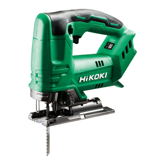
PRODUCT NAME
18 V Cordless Jig Saw
Model 135 mm (5-5/16")
CONTENTS
REPAIR GUIDE ---------------------------------------------------------------------------------------------------------------- 1
1. Precautions on disassembly and reassembly ----------------------------------------------------------- 1
• Disassembly ---------------------------------------------------------------------------------------------------- 1
• Reassembly ---------------------------------------------------------------------------------------------------- 4
• Lubrication points and type of lubricant ------------------------------------------------------------------ 5
• Tightening torque ---------------------------------------------------------------------------------------------- 6
• Checking after reassembly --------------------------------------------------------------------------------- 6
• Wiring diagram ------------------------------------------------------------------------------------------------- 7
CJ 18DA
Overseas Sales Management Dept.
CONFIDENTIAL
Sep. 2020
Page
C
Advertisement

Related Manuals for Hitachi CJ 18DA


Summary of Contents for Hitachi CJ 18DA
-
Page 1: Table Of Contents
CONFIDENTIAL Sep. 2020 PRODUCT NAME 18 V Cordless Jig Saw CJ 18DA Model 135 mm (5-5/16”) Page CONTENTS REPAIR GUIDE ---------------------------------------------------------------------------------------------------------------- 1 1. Precautions on disassembly and reassembly ----------------------------------------------------------- 1 • Disassembly ---------------------------------------------------------------------------------------------------- 1 • Reassembly ---------------------------------------------------------------------------------------------------- 4 • Lubrication points and type of lubricant ------------------------------------------------------------------ 5 •... -
Page 2: Repair Guide
1. Precautions on disassembly and reassembly [Bold] numbers in the description below correspond to the item numbers in the parts list and exploded assembly diagram for the Model CJ 18DA. Disassembly 1. Removal of the base Loosen the Hex. - Page 3 Fig. 3 4. Disassembly of the plunger ass’y (1) Remove the D6 Pin [46] from the Gear Holder Ass’y [47]. Remove Plunger Holder (A) [31] from the plunger ass’y. (2) Loosen two Seal Lock Hex. Socket Hd. Bolts M3 x 6 [18] and remove the Plunger Cover [17] and Plunger (A) [32].
- Page 4 5. Removal of the gear holder (1) Pull out Connecting Piece (A) [33] and Needle Bearing [34] from the Gear [36]. (2) Remove the Retaining Ring for D7 Shaft [35] from the tip of the spindle. (3) Remove the Gear [36], Balance Weight [37], Orbital Cam [38] and Washer (A) [23] in this order. (4) Remove the Motor [13] press-fitted in the Gear Holder Ass’y [47].
-
Page 5: Reassembly
Reassembly Perform reassembly by reversing the disassembly procedure. However, special attention should be given to the following items. 1. Mounting the change knob Mount Spring (C) [27] and Steel Ball 5/32 [41] to the inside of the Change Knob [42] as described below. (1) Apply grease (Nippeco SEP-3A) to the Steel Ball 5/32 [41], and then put the Steel Ball 5/32 [41] in the concave portion as shown in the figure below. -
Page 6: Lubrication Points And Type Of Lubricant
Fig. 7 [31] [17] [18] [19] [32] [20] [21] [25] [22] [23] [24] [26] [27] [28] [29] [30] Lubrication points and type of lubricant Apply specified amount of grease to the following portions. Nippeco SEP-3A grease • Entire circumference of the Gear [36], particularly its teeth •... -
Page 7: Tightening Torque
Tightening torque Tightening torque Item Part name used N•m kgf•cm Tapping Screw (W/Flange) D4 x 20 (Black) 1.96±0.49 20±5 [12] Tapping Screw (W/Flange) D3 x 20 0.88±0.10 9±1 [18] Seal Lock Hex. Socket Hd. Bolt M3 x 6 2.45±0.49 25±5 [45] Special Bolt 2.76±0.29... -
Page 8: Wiring Diagram
Wiring diagram Connect the internal wires correctly as illustrated in the diagrams below. If the internal wires are incorrectly connected, the motor may not turn or other problems could occur. Fig. 8 • Wiring diagram Red internal wire (soldering) Black internal wire (soldering) (Europe, Australia, and New Zealand) Red internal wire... - Page 9 Fig. 9 • Connecting diagram DC-speed control switch Noise suppressor S G T Black (–) Black White White Black Battery terminal – Indicator ass’y For Europe, Australia, and New Zealand DC-speed control switch Ferrite core Noise suppressor S G T Black (–) Black...
- Page 10 CJ18DA Rev.1...
- Page 11 ITEM CODE DESCRIPTION REMARKS USED 376450 HOUSING (A).(B) SET 376450M HOUSING (A).(B) SET FOR USA, CAN 336856 PUSHING BUTTON 376452 SWITCH TERMINAL SET 376029 BATTERY BSL 1850C (EUROPE, AUS, NZL) INCLUD. 502 376314 BATTERY BSL 1850C (THA) INCLUD. 502 376482 GRIP COVER NAME PLATE 301653 TAPPING SCREW (W/FLANGE) D4 X 20 (BLACK) 376484 GUARD BAR...
- Page 12 ITEM CODE DESCRIPTION REMARKS USED 372814 GREASE (NIPPECO BC-4) 75 G 325149 GREASE (MOLUB-ALLOY NO. 777-1) 75 G 879336 JIG SAW BLADES NO. 11 (5 PCS.) 879337 JIG SAW BLADES NO. 12 (5 PCS.) 879338 JIG SAW BLADES NO. 15 (5 PCS.) 879339 JIG SAW BLADES NO.
Need help?
Do you have a question about the CJ 18DA and is the answer not in the manual?
Questions and answers