Table of Contents
Advertisement
Quick Links
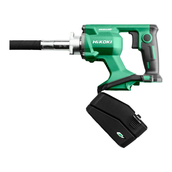
PRODUCT NAME
36 V Cordless Concrete Vibrator
UV 3628DA
Model
CONTENTS
TROUBLESHOOTING GUIDE --------------------------------------------------------------------------------------------- 1
REPAIR GUIDE ---------------------------------------------------------------------------------------------------------------- 2
1. Precautions on disassembly and reassembly ----------------------------------------------------------- 2
• Disassembly ------------------------------------------------------------------------------------------------- 2
• Reassembly -------------------------------------------------------------------------------------------------- 4
• Tightening torque ------------------------------------------------------------------------------------------- 6
• Checking after reassembly ------------------------------------------------------------------------------- 6
• No-load current ---------------------------------------------------------------------------------------------- 6
CONFIDENTIAL
Overseas Sales Management Dept.
Jun. 2020
Page
U
Advertisement
Table of Contents

Related Manuals for Hitachi UV 3628DA


Summary of Contents for Hitachi UV 3628DA
-
Page 1: Table Of Contents
CONFIDENTIAL Jun. 2020 PRODUCT NAME 36 V Cordless Concrete Vibrator UV 3628DA Model CONTENTS Page TROUBLESHOOTING GUIDE --------------------------------------------------------------------------------------------- 1 REPAIR GUIDE ---------------------------------------------------------------------------------------------------------------- 2 1. Precautions on disassembly and reassembly ----------------------------------------------------------- 2 • Disassembly ------------------------------------------------------------------------------------------------- 2 • Reassembly -------------------------------------------------------------------------------------------------- 4 • Tightening torque ------------------------------------------------------------------------------------------- 6 •... -
Page 2: Troubleshooting Guide
TROUBLESHOOTING GUIDE NOTE: Before troubleshooting, be sure to wipe off all dust, water, and other foreign matter from the internal parts, and then dry the parts completely. Trouble Cause Checking Corrective action 1. Motor Flexible shaft is locked. Turn on the switch and check whether the switch Replace the flexible does not panel indicates overload status or not. -
Page 3: Repair Guide
[Bold] numbers in the description below correspond to the item numbers in the parts list and exploded assembly diagram of the Model UV 3628DA. Some abbreviated part names are used in this manual. See the parts list for the full names. - Page 4 2. Disassembly of housing (A).(B) set (1) Remove the four Tapping Screws (W/Flange) D5 x 20 [1] from the Front Cover [2]. Remove the twelve Tapping Screws (W/Flange) D3 x 16 [8] from Housing (A).(B) Set [9]. Remove housing (B) and Battery Cover [13] from housing (A).
-
Page 5: Reassembly
Reassembly Conduct reassembly by reversing the disassembly procedure but note the following. 1. Reassembly of the power supply section • Reassembly of the power supply section (1) Fit the flange in the groove. Position the lever to the inside. Align the corner of the stator insulator with the corner of Do not put the signal wire on... - Page 6 • Reassembly of the power supply section (2) Fit the protrusions of the Stator FET PCB Ass’y [6] in the mating portions of the housing. 2. Mounting the flexible shaft (1) Fix the shaft sleeve with pliers. Tighten the shaft of the Rotor Ass’y [5] with a wrench (8 mm) fitting on its width across flats portion until it contacts the shaft sleeve as shown in the figure below.
-
Page 7: Tightening Torque
Tightening torque Tightening torque Item Part name used N•m kgf•cm Tapping Screw (W/Flange) D5 x 20 (Black) 1.3±0.3 13±3 Tapping Screw (W/Flange) D3 x 16 (Black) 3±0.5 30±5 ― Shaft sleeve (flexible shaft) 5±1 50±10 ― Hose gland (reference) 45±10 450±100 Checking after reassembly Check the following after reassembly:... - Page 8 M O D E L UV3628DA Rev.1...
- Page 9 ITEM CODE DESCRIPTION USED REMARKS 302089 TAPPING SCREW (W/FLANGE) D5 X 20 (BLACK) 376121 FRONT COVER 629VVM BALL BEARING 629VV 958915 WASHER (A) 361129 ROTOR ASS'Y 341067 STATOR FET PCB ASS'Y NAME PLATE 313687 TAPPING SCREW (W/FLANGE) D3 X 16 (BLACK) 376120 HOUSING (A).(B) SET 376123 SWITCH COVER 376124 ON LOCK COVER...
Need help?
Do you have a question about the UV 3628DA and is the answer not in the manual?
Questions and answers