Table of Contents
Advertisement
Quick Links
For the operator
Operating Instructions
1
About This Documentation ................................................................................4
1.1 Retention of documents ..............................................................................................................4
1.2 Symbols used in this document ....................................................................................................4
1.3 Name plate ................................................................................................................................4
2
Safety Instructions and Regulations .................................................................5
3
Notes on Installation and Operation .................................................................5
3.1 Intended use ..............................................................................................................................5
3.2 Factory warranty and liability ......................................................................................................6
3.3 Service .......................................................................................................................................6
4
Operation ............................................................................................................6
4.1 Overview of controls and displays ................................................................................................6
4.2 LED displays ...............................................................................................................................7
4.4 Level 1 menu - Display mode ......................................................................................................8
4.5 Level 2 menu - Confi guration mode ............................................................................................8
4.6 Night time start switch .............................................................................................................10
4.7 The RS485 interface .................................................................................................................10
4.8 Display .....................................................................................................................................10
5
Accessories ........................................................................................................ 13
6
Troubleshooting ................................................................................................ 14
7
Recycling and Disposal ..................................................................................... 16
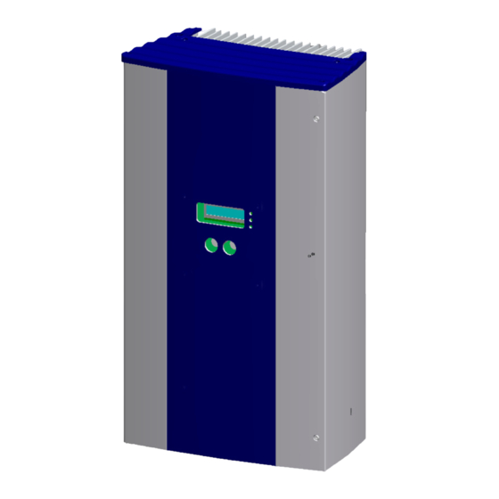
blueplanet Operating and Installation Instructions 1502x - 2502x
For authorized electricians
Installation Instructions
I n st ru ct io n s b eg i n o n p a g e 1 8
blueplanet 1502x / 2502x
Page 3
Advertisement
Chapters
Table of Contents
Troubleshooting

Subscribe to Our Youtube Channel
Related Manuals for Kaco blueplanet 1502 Series


Summary of Contents for Kaco blueplanet 1502 Series
-
Page 1: Table Of Contents
For the operator For authorized electricians Operating Instructions Installation Instructions I n st ru ct io n s b eg i n o n p a g e 1 8 blueplanet 1502x / 2502x About This Documentation ................4 1.1 Retention of documents ......................4 1.2 Symbols used in this document ....................4 1.3 Name plate ..........................4 Safety Instructions and Regulations ..............5... -
Page 2: About This Documentation
By purchasing an inverter from KACO new energy GmbH, you have opted for a reliable, high-performance technology and will profi t from KACO new energy’s many years of experience in CAUTION indicates a hazardous situation which, the fi eld of current inverter technology and power electronics. -
Page 3: Safety Instructions And Regulations
If necessary, your solar installer or KACO new energy GmbH will assist you. Damage reports must be received by the shipping company in writing within six days of receipt of the goods. -
Page 4: Factory Warranty And Liability
3.2 Factory warranty and CAUTION liability KACO new energy GmbH issues a warranty of ten years or 120 Incorrect use is prohibited. months on the blueplanet inverter starting from the date of installation, but at most 130 months after shipment by KACO new energy GmbH. -
Page 5: Led Displays
Operation 4.2 LED displays 4.3 Keys “1” and “2” The inverter is equipped with three LEDs that give information about the various operating statuses as follows: Figure 3: blueplanet control keys Figure 2: LED displays Key “1” is used to switch between the various displays for LED (1) (green): measured values and data. -
Page 6: Level 1 Menu - Display Mode
Operation Temperature inside unit 4.4 Level 1 menu – Display Displays the current heat sink temperature. If the unit becomes mode too hot, the unit will reduct power output or switch off. The display menu is shown once the blueplanet inverter starts Counter yield up. - Page 7 KACO proLOG, watchDOG or Language selection other monitor. If several inverters are connected to a KACO proLOG, watchDOG or other monitor each address may only be used once. It is possible to monitor 32 blueplanet inver- Clear the grid-feed counter ters with one KACO proLOG.
-
Page 8: Night Time Start Switch
Several inverters can be monitored over this interface at the same time. Using the KACO proLOG, watchDOG or other monitoring device you can receive yield and operating data as well as error messages by SMS (text message) or e-mail. - Page 9 Operation Operating States Status Explanation Comment Inverter has just switched on Only for a brief period after being fi rst switched on in the morning. Waiting to start Grid parameters and generator voltage are checked. Waiting to switch off tus before it switches over to night shutdown mode. Constant voltage regulator The inverter continues to operate with minimum MPP voltage when the grid- feed power is low.
- Page 10 Operation Status Display Explanation Temperature too high inside The temperature in the unit has become too high (> 176 °F). When the internal reaches 158 °F, the inverter limits the power. An internal temperature of 176 °F is only reached if convection cooling is impeded by external factors, e.g. by covering the cooling fi...
-
Page 11: Accessories
5 Accessories KACO-watchDOG The KACO-watchDOG card is the integrated communication option from KACO for monitoring your PV installation. Up to three inverters can be monitored with one affordable card. KACO offers its customers a comprehensive range of helpful accessories. The array of products includes monitoring, display,... -
Page 12: Troubleshooting
Troubleshooting 6 Troubleshooting In line with our continuously expanding quality assurance system, we endeavor to eliminate all errors and faults. You have purchased a product which left our factory in proper condition. Each individual unit has successfully passed an endurance test as well as extensive tests for the purpose of assessing the operating behavior and the protective equipment. - Page 13 Troubleshooting Error Cause of error Troubleshooting/Explanation The inverter stops sup- Faulty grid separation relay in Although there is suffi cient sunlight, the inverter feeds into the grid plying power to the grid the inverter. only for a few seconds before switching off again. During the short shortly after being switched grid-feed period, the inverter shows that the power being fed into on, even though there is...
-
Page 14: Recycling And Disposal
For the most part, both the inverter and the corresponding transport packaging are made from recyclable materials. KACO does it’s best to ensure our vendors follow a low carbon manufacturing process as we do ourselves. It is not always possible but if you have questions about our products or the components in our products don’t hesitate to call +1 (866) - Page 15 For authorized electricians Recycling and Disposal Installation Instructions About This Documentation ................18 1.1 Retention of documents ......................18 1.2 Symbols used in this document ....................18 1.3 Name plate ..........................18 Safety Instructions and Regulations ............... 19 Technical Data ....................20 Unit Description ....................23 4.1 Included in box .........................23 4.2 Designing the PV array ......................23 4.3 Protection concepts ........................24...
-
Page 16: About This Documentation
About This Documentation 1 About This Documenta- NOTICE tion The following notes guide you through all of the documenta- Failure to observe a warning indicated in this manner may tion. Additional documents are applicable in conjunction with lead to damage to property. these operating and installation instructions. -
Page 17: Safety Instructions And Regulations
Safety Instructions and Regulations 2 Safety Instructions and The proper and safe operation of this unit requires proper transportation, storage, assembly and installation, as well as Regulations careful operation and maintenance. Only authorized electricians who have read and fully under- stood all of the safety instructions contained in these operat- ing and installation instructions, as well as other instructions DANGER... -
Page 18: Technical Data
Technical Data 3 Technical Data Input – Electrical data Model 1502x 2502x DC rated power 1600 W 2650 W Max. recommended 2000 W 3000 W PV generator power MPP range 125-400 V 200-450 V No-load voltage 550 V 550 V Stand-by from Stand-by from Monitoring input voltage... - Page 19 Technical Data Inverter – Electrical data Model 1502x 2502x 96.0 % @ 240 V Max. degree of effi ciency 95.9 % @ 240 V 95.5 % @ 208 V 95.6 % @ 208 V CEC degree of effi ciency 95.5 % @ 240 V 95.0 % @ 208 V 95.5 % @ 240 V 95 0 % @ 208 V...
- Page 20 Technical Data Inverter – Mechanical and technical data Model 1502x 2502x LEDs: PV generator (green) Grid-feed (green) Visual displays Fault (red) LCD (2 x 16 characters) Controls 2 keys for display operation and confi guration of parameters Cable connection via conduit fi ttings using 3/4” or 1/2” blind plug Connections Terminals accept up to AWG 10, 75’C, copper wire.
-
Page 21: Unit Description
PV installation. To achieve an optimum yield from the installation, half of the strings must be installed on the east KACO Calc PRO, a dimensioning program for the easy selec- side of the roof; the second half on the west side. -
Page 22: Protection Concepts
Unit Description 4.3 Protection concepts 4.5 Inverter knockout dimensioning The following monitoring and protective functions are inte- grated into blueplanet inverters: – Overvoltage conductors/varistors to protect the power semiconductors from high-energy transients on the grid side. – Temperature monitoring of the heat sink. –... -
Page 23: Installation And Start-Up
Installation and Start-Up 5 Installation and Start- – The unit is designed for vertical wall installation. – Air must be allowed to circulate freely around the housing and through the heat sink on the rear side. – If the inverter is built into a switching cabinet or similar, provide forced ventilation to ensure that heat is suffi... -
Page 24: External Dc Switch And Ac Disconnect
Installation and Start-Up 5.3 External DC switch and AC nect, suitable for use for the prevailing conditions, and limits the grouping of disconnects to six per enclosure. Section D, disconnect permits utility interactive, or grid tied inverters to be located in areas that are not readily accessible, and details the switch requirements. -
Page 25: Grounding The Inverter
Installation and Start-Up The GFDI fuse is located on the bottom plate of the inverter. Grounding multiple inverters: Use a DC GE (Grounding Electrode – ground rod) and run an When a ground fault occurs this fuse will open causing the appropriately sized conductor from the DC GE to the AC GE. - Page 26 Installation and Start-Up Clamp the enclosed cable bridge in the upper GFDI Positive Grounded System terminal and the DC+(Figure 13) or DC-connection NOTE (Figure 14). Consult the module manufacturer for infor- mation on which generator pole should be earthed. Negative Grounded System (Factory Default) In this confi...
-
Page 27: Connecting To The Public Grid
Installation and Start-Up 5.5 Connecting to the Public ACT ION Grid The inverter can be installed on the following grid-types: Before connecting the PV generator to the blueplanet, check that the PV generator is not grounded. – Measure the DC voltage between the protective ground (PG) and the positive lead and between the protective ground (PG) and the negative lead of the PV generator. -
Page 28: Electrical Connection
Installation and Start-Up Country setting on the display: USA 240 V no neut 5.6 Electrical connection General information The electrical connections can be established after the inverter is installed in its fi xed location. Knockouts are provided on the 120° sides, bottom, and rear of the inverter bottom plate to easily run conduit to the desired locations. - Page 29 Installation and Start-Up (A) Grid Connection AC Connections are a 3 or 4 wire connection. In 4 wire systems incorporating a Neutral there will be the following connections; Line-1, Line-2, Neutral, and Ground. In 3 wire systems not incorporating a Neutral there will be the following connections; Line-1, Line-2, and Ground.
- Page 30 Installation and Start-Up N OT E Be sure to use cables with a suffi ciently large cross-section to avoid excessive line impedance between the building’s distribution box and the respective blueplanet unit. When the line impedance is high, i.e. long AC-side leads, the voltage at the line terminals of the inverter will increase as power is being fed in to the grid.
-
Page 31: Interfaces
Terminal B is connected in the same manner. A twisted, shielded data cable is required for this. The connection to the KACO proLOG is established similarly to the interconnection of inverters. A connection diagram is displayed in Figure 26. -
Page 32: Starting Up The Inverter
(see code must be obtained from KACO support. Please have Operating Instructions). the inverter serial number available when calling to obtain the pass code. - Page 33 Installation and Start-Up Explanation of the individual parameters: Country selection During the initial start-up, the country can be selected and changed again without entering a code. If no entry is made for 10 minutes or the unit is switched off, the country selection is stored.
-
Page 34: Two-Stage Shutdown In Accordance With Ieee
Two-Stage Shutdown in Accordance with IEEE 6 Two-Stage Shutdown in Accordance with IEEE (standard values for < 30 kW) The shutdown times and the shutdown values for the line voltage and frequency can be narrowed to within a specifi ed range for the blueplanet 02x series inverters. -
Page 35: Blueplanet As Part Of A Pv Installation
blueplanet as Part of a PV Installation 7 blueplanet as Part of a PV Installation 7.1 Design of installation A sample design of a grid-connected PV installation using a blueplanet is shown below in the overview circuit diagram. PV-Array PV-Array External External DC switch... - Page 36 blueplanet as Part of a PV Installation A summary of the components: DC terminal point: Two PV strings can be connected in parallel either at a DC terminal point between the solar generator and the inverter or directly on the inverter (terminals for three strings are provided on the inverter).
-
Page 37: Installation With Multiple Inverters On A Three Phase System
blueplanet as Part of a PV Installation 7.2 Installation with multiple inverters on a three phase system Observe the following regarding installations with multiple inverters on a three phase system: Asymmetric grid-feed: The power should be distributed as equally as possible over the three phases. In the US, typically the asymmetry between the phases may be a maximum of 6 kW (This number can vary depending on utility transformer size and codes). -
Page 38: Troubleshooting
Troubleshooting If the measures described in this guide do not assist in clearing the fault, please notify KACO technical support at +1(866) 522-6765. In order for our factory customer service department to respond in an appropriate and expeditious manner, some details are imperative: Details pertaining to the inverter –... -
Page 39: Effi Ciency Curves
Effi ciency curves 9 Effi ciency curves 125 Vdc 195 Vdc 400 Vdc 100% % of Rated Output Power Figure 30: Effi ciency curve 1502x / 240 V 125 Vdc 195 Vdc 400 Vdc 100% % of Rated Output Power Figure 31: Effi... - Page 40 Effi ciency curves 200 Vdc 265 Vdc 450 Vdc 100% % of Rated Output Power Figure 32: Effi ciency curve 2502x / 240 V 200 Vdc 265 Vdc 450 Vdc 100% % of Rated Output Power Figure 33: Effi ciency curve 2502x / 208 V Page 42 blueplanet Operating and Installation Instructions 1502x - 2502x...
-
Page 41: Compliance Certifi Cates
Compliance Certifi cates 10 Compliance Certifi cates blueplanet Operating and Installation Instructions 1502x - 2502x Page 43... - Page 42 Recycling and Disposal Page 44 blueplanet Operating and Installation Instructions 1502x - 2502x...
Need help?
Do you have a question about the blueplanet 1502 Series and is the answer not in the manual?
Questions and answers