Table of Contents
Advertisement
Quick Links
Please follow the instructions in this manual to obtain the optimum results from this unit.
We also recommend that you keep this manual handy for future reference.
PUBLIC ADDRESS SYSTEM
T-1S60
POWER AMPLIFIER
SIGNAL
CLIP
PROT
TEMP
POWER
VOLUME
5
4
6
3
7
ON
2
8
OFF
1
9
0
10
T-1S120
POWER AMPLIFIER
SIGNAL
CLIP
PROT
TEMP
POWER
VOLUME
5
4
6
3
7
ON
2
8
OFF
1
9
0
10
T-1S240
POWER AMPLIFIER
SIGNAL
CLIP
PROT
TEMP
POWER
VOLUME
5
4
6
3
7
ON
2
8
OFF
1
9
0
10
T-1S60
T-1S120
T-1S240
POWER AMPLIFIER
Advertisement
Table of Contents

Subscribe to Our Youtube Channel
Related Manuals for ITC T-1S60


Summary of Contents for ITC T-1S60
- Page 1 PUBLIC ADDRESS SYSTEM T-1S60 T-1S120 T-1S240 POWER AMPLIFIER T-1S60 POWER AMPLIFIER SIGNAL CLIP PROT TEMP POWER VOLUME T-1S120 POWER AMPLIFIER SIGNAL CLIP PROT TEMP POWER VOLUME T-1S240 POWER AMPLIFIER SIGNAL CLIP PROT TEMP POWER VOLUME Please follow the instructions in this manual to obtain the optimum results from this unit.
-
Page 2: Table Of Contents
TABLE OF CONTENTS 1. SAFETY PRECAUTIONS ..................3 2. GENERAL DESCRIPTION ..................5 3. FEATURES ....................... 5 4. NOMENCLATURE AND FUNCTIONS 4. 1 Front Panel ........................6 4. 2 Rear Panel........................7 5. CONNECTIONS ......................8 6. OPERATION GUIDANCE 6. 1 POWER SWITCH & POWER INDICATOR ...............9 6. -
Page 3: Safety Precautions
1. SAFETY PRECAUTIONS Be sure to read the instructions in this section carefully before use. Make sure to observe the instructions in this manual as the conventions of safety symbols and messages regarded as very important precautions are included. We also recommend you keep this instruction manual handy for future reference. Safety Symbol and Message Conventions Safety symbols and messages described below are used in this manual to prevent bodily injury and property damage which could result from mishandling. - Page 4 When removing the power cord, be sure to hold its plug to pull. Contact your ITC dealer as to the cleaning. If dust is allowed to accumulate in the unit over a long Do not block the ventilation slots in the unit's cover.
-
Page 5: General Description
2. GENERAL DESCRIPTION This range of power amplifiers are designed for general commercial and industrial public address ap- plications. Rack mount design in 2U type, rated power ranges from 60W to 240W which provides a wide selection to meet different size sound system needs. Both balanced and unbalanced line inputs make it selectable for installer, balanced line output feeds to another power amplifier as well as secu- res the signal transmission is less noise and longer distance. -
Page 6: Nomenclature And Functions
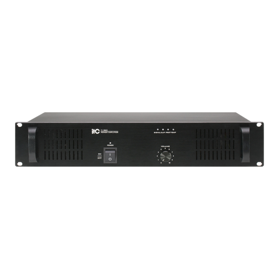
4. NOMENCLATURE AND FUNCTIONS 4.1 FRONT PANEL POWER SWITCH On top of the opening Power Press the end, power shut down VOLUME Channel volume control TEMP The protection indicator will be light on when the inside temperature is over 90C, the output will be cut to protect the amplifier from damage. -
Page 7: Rear Panel
NOMENCLATURE AND FUNCTIONS 4.2 REAR PANEL INPUTS LINK XLR BAL 1-GND 2-HOT+ 3-COLD- OUTPUTS COM 4-16 70V 100V INPUTS LINK LIFT 8. ~220-240V 50/60Hz POWER INPUT 9. COMMON SPEAKER OUTPUT Connectors for 4 ohms or 70V and 100V speaker 10. LINE INPUT (XLR) Music signal input balance 11. -
Page 8: Connections
5. CONNECTIONS SPEAKER CONNECTIONS 100V 4~16 100V 4~16 100V 4~16 (T-1S60) (T-1S60) (T-1S120) (T-1S120) (T-1S240) (T-1S240) 4~16 LINE 70V LINE 100V LINE 70V/ 4~16... -
Page 9: Power Switch & Power Indicator
6. OPERATION GUIDANCE 6.1 POWER SWITCH & POWER INDICATOR T-1S60 POWER AMPLIFIER Picture 1.1 Electricity power on when power switch is at position and power indicator light in blue. Electricity power off when power switch is at position and power indicator extinguished. -
Page 10: Xlr Line Output
OPERATION GUIDANCE 6.3 XLR LINE OUTPUT INPUTS LINK XLR BAL 1-GND 2-HOT+ 3-COLD- OUTPUTS COM 4-16 70V 100V INPUTS LINK LIFT INPUTS LINK XLR BAL 1-GND 2-HOT+ 3-COLD- INPUTS LINK ~220V 50Hz ~220V 50Hz T2AL 250V T2AL 250V LIFT OUTPUTS COM 4-16 70V 100V USE ONLY WITHA 250VFUSE... -
Page 11: Speaker Outputs 4~16 & 70V& 100V
OPERATION GUIDANCE SPEAKER OUTPUTS 4~16 & 70V& 100V INPUTS LINK XLR BAL 1-GND 2-HOT+ 3-COLD- OUTPUTS COM 4-16 70V 100V INPUTS LINK LIFT LIFT OUTPUTS LIFT OUTPUTS LIFT OUTPUTS COM COM COM 4-16 70V 100V COM COM COM 4-16 70V 100V COM COM COM 4-16 70V 100V... -
Page 12: Machine Operation
7. MACHINE OPERATION MIC INPUT CHANNEL 1~3 This is a special connector which will accept 3-conductor XLR. These inputs are suitable to receive signal from microphones level devices. MIC JACK (XLR JACK) LINE JACK (TRS PHONE JACK) Pin 1:GROUND Sleeve:GROUND Pin 2:HOT(+) Tip:HOT(+) Pin 3:COLD(-) -
Page 13: Applications
8. APPLICATIONS REAR PANEL CONNECTIONS... -
Page 14: Block Diagram
9. BLOCK DIAGRAM... -
Page 15: Specifications
10. SPECIFICATIONS POWER AMLIFIER MODEL T-1S60 T-1S120 T-1S240 RATED POWER OUTPUT 120W 240W SPEAKER OUTPUTS 4~16 ,70V/100V INPUT SENSITIVITY 775mV/0dB FREQUENCY RESPONSE 50Hz~18KHz S/N RATIO Better than 105dB T.H.D Less than 1% at 1KHz, 1/3 rated power Power switch, volume control... -
Page 16: Dimensional Diagram
11. DIMENSIONAL DIAGRAM UNIT :mm INPUTS LINK XLR BAL 1-GND 2-HOT+ 3-COLD- OUTPUTS LIFT COM 4-16 70V 100V INPUTS LINK UNIT :mm Over Over... - Page 17 PUBLIC ADDRESS SYSTEM PUBLIC ADDRESS SYSTEM VersionV0.4...
Need help?
Do you have a question about the T-1S60 and is the answer not in the manual?
Questions and answers