
Related Manuals for Iskra iMT416


Summary of Contents for Iskra iMT416
- Page 1 Programmable AC Voltage Transducer iMT416 Programmable AC Current Transducer iMT418 July 2021 • Version 1.00 User’s Manual...
- Page 2 Programmable AC Voltage Transducer iMT416 Programmable AC Current Transducer iMT418 User and Installation manual User’s Manual...
- Page 3 ISKRA d.o.o. assumes no responsibility in connection with installation and use of the product. If there is any doubt regarding installation and use of the system in which the device is used for measuring or supervision, please contact a person who is responsible for installation of such system.
- Page 4 Used symbols on devices’ housing and labels SYMBOL EXPLANATION WARNING Indicates situations where careful reading of this manual is required and following requested steps to avoid potential injury is advised. Double insulation in compliance with the SIST EN 61010−1 standard. Compliance of the product with directive 2002/96/EC, as first priority, the prevention of waste electrical and electronic equipment (WEEE), and in addition, the reuse, recycling and other forms of recovery of such wastes so as to reduce the...
-
Page 5: Table Of Contents
ASIC DESCRIPTION AND OPERATION Table of contents BASIC DESCRIPTION AND OPERATION NTRODUCTION ESCRIPTION OF THE DEVICE URPOSE AND USE OF DIFFERENT TYPES OF MEASURING TRANSDUCERS CONNECTION NTRODUCTION OUNTING LECTRICAL CONNECTION OMMUNICATION CONNECTION ONNECTION OF AUXILIARY POWER SUPPLY SETTINGS NTRODUCTION EN SOFTWARE ETTING PROCEDURE ENERAL SETTINGS (COM1) - Page 6 ASIC DESCRIPTION AND OPERATION ABBREVIATION/GLOSSARY APPENDICES APPENDIX A: MODBUS COMMUNICATION PROTOCOL APPENDIX C: CALCULATIONS & EQUATIONS User’s Manual...
-
Page 7: Basic Description And Operation
ASIC DESCRIPTION AND OPERATION BASIC DESCRIPTION AND OPERATION The following chapter presents basic information about multifunction transducers required to understand its purpose, applicability and basic features connected to its operation. In this chapter you will find: NTRODUCTION ESCRIPTION OF THE DEVICE URPOSE AND USE OF DIFFERENT TYPES OF MEASURING TRANSDUCERS User’s Manual... -
Page 8: Introduction
ASIC DESCRIPTION AND OPERATION Introduction iMT416 and iMT418 are programmable AC voltage / current transducers with minimal differences in functionality. Where there are some characteristic features that denote iMT416 or iMT418 symbol next to data. 1.1.1 Description of symbols Subchapter Symbols next to the subchapters indicate accessibility of functions described. -
Page 9: Description Of The Device
ASIC DESCRIPTION AND OPERATION Description of the device Programmable AC measuring transducer is intended for measuring, analyzing and monitoring single- phase voltage or current. Also frequency measurement of voltage or current signal is supported. It measures TRMS values by means of fast sampling of voltage and current signals, which makes instrument suitable for acquisition of transient events. -
Page 10: Purpose And Use Of Different Types Of Measuring Transducers
1.3.1 Programmable AC Voltage transducer iMT416 iMT416 is intended for measuring and monitoring single-phase voltage or frequency. Voltage input is electrically insulated from the system by means of voltage transformer. It measures TRMS voltage value by means of fast sampling of voltage signals, which makes instruments suitable for acquisition of transient events. -
Page 11: Connection
Only a qualified person shall therefore perform connection. Iskra d.o.o. does not take any responsibility regarding the use and connection. If any doubt occurs regarding connection and use in the system, which device is intended for, please contact a person who is responsible for such installations. -
Page 12: Introduction
(connection mode, current and voltage transformers ratio, etc.). Mounting (iMT416/418 Programmable AC measuring transducer is designed for panel mounting. It should be mounted on a 35 mm DIN rail by means of one plastic fastener. Before installation fastener should be in open position (pulled). -
Page 13: Communication Connection
INTENTED ONLY FOR QUICK SETUP BY MIQEN SOFTWARE PRIOR INSTALLING THE INSTRUMENT. USB connector is placed on the bottom of the iMT416/418, behind removable cap. After installation it is not accessible any more. When connected, iMT416/418 is powered by USB port. - Page 14 PLEASE NOTE When iMT416/418 is connected to a PC through USB communication for the first time, a user is prompted to install a driver. The driver can be downloaded from the Iskra d.o.o. web page https://www.iskra.eu/en/. With this driver installed, USB is redirected to a serial port, which should be selected when using MiQen software.
-
Page 15: Connection Of Auxiliary Power Supply
CONNECTION Connection of auxiliary power supply Programmable AC measuring transducer has universal (AC/DC) auxiliary power supply. Information on electric consumption is given in chapter Technical data on page 22. Auxiliary supply is connected through two screw-in connectors. Universal (24 VDC – 300 VDC; 40 VAC – 276 VAC) or Transformer (110, 230 VAC), which should be chosen at placing the order. -
Page 16: Settings
SETTINGS SETTINGS A setting structure, which is similar to a file structure in an explorer is displayed in the left part of the MiQen setting window. Available settings of that segment are displayed in the right part by clicking any of the stated parameters. -
Page 17: Introduction
PC. MiQen software MiQen software is a tool for a complete programming and monitoring of ISKRA measuring instruments, connected to a PC via serial communication or USB communication. A user-friendly interface consists of five segments: devices management, instrument settings, real-time measurements, data analysis and software upgrading. -
Page 18: Setting Procedure
PLEASE NOTE More information about MiQen software can be found in MiQen Help system! You can download freeware MiQen (standard edition) from: www.iskra.eu Setting procedure In order to modify instrument settings with MiQen, current parameters must be loaded first. Instrument settings can be acquired via a communication link (serial or USB) or can be loaded off-line from a file on a local disk. - Page 19 SETTINGS 3.4.4 Maximum demand calculation (MD mode, iMT418) The instrument provides maximum demand values from a thermal function demand values. A thermal function assures exponent thermal characteristic based on simulation of bimetal meters. Maximal values and time of their occurrence are stored in device. A time constant (t. c.) can be set from 1 to 255 minutes and is 6 −...
-
Page 20: Serial Communication (Com1)
(depending on a serial number of the meter). The BP password is available in the user support department in ISKRA d.o.o., and is entered instead of the password PL1 or/and PL2. Do not forget to state the meter serial meter when contacting the personnel in Iskra d.o.o.. - Page 21 SETTINGS 3.6.1 Password setting A password consists of four letters taken from the British alphabet from A to Z. When setting a password, only the letter being set is visible while the others are covered with *. Two passwords (PL1, PL2) and the time of automatic activation could be set. Password modification A password can be modified;...
-
Page 22: Inputs And Outputs
SETTINGS Inputs and outputs Module settings depend on built-in modules. 3.7.1 Analogue output module Unipolar analogue output is fully programmable and can be set to any of 6 ranges. Output parameter Set the measured parameter to be transformed onto the analogue output. Output range Defines analogue output full-scale ranges: DC current output... - Page 23 SETTINGS Example of settings with linear and bent characteristic: Average interval for analogue output Defines the average interval for measurements on the analogue output. Available settings are from 1 period (0.02 sec by 50 Hz) up to 256 periods (5.12 sec by 50 Hz). 3.7.2 Reset maximal MD values (iMT418) Current and stored MDs are reset.
-
Page 24: Measurements
MEASUREMENTS MEASUREMENTS In the following chapters the device operation is explained more in detail. XPLANATION OF BASIC CONCEPTS ALCULATION AND DISPLAY OF MEASUREMENTS RESENT VALUES User’s Manual... -
Page 25: Explanation Of Basic Concepts
MEASUREMENTS Online measurements 4.2.1 Daily energy consumption profile In the graphical form, the measurements of total energy and daily consumption profile of energy of all three phases are represented. The daily energy consumption profile measures a 15-minute average of the active power. Press the System symbol to observe the measurements of total energy. -
Page 26: Present Values
MEASUREMENTS Present values Voltage Instrument measures real effective (trms) value of phase voltage (U), connected to the meter. Voltage measurement is available via communication. 4.5.1 Current Instrument measures real effective (trms) value of phase currents, connected to current input. Current measurement is available via communication. 4.5.2 Frequency Network frequency is calculated from time periods of measured voltage. -
Page 27: Technical Data
TECHNICAL DATA TECHNICAL DATA In following chapter all technical data regarding operation of multifunction transducers is presented. PPLIED STANDARDS CCURACY ECHANICAL CHARACTERISTICS OF INPUT LECTRICAL CHARACTERISTICS OF INPUT ONNECTION NALOGUE OUTPUT OMMUNICATION LECTRONIC FEATURES AFETY FEATURES IMENSIONS User’s Manual... -
Page 28: Applied Standards
Maximum current (iMT418) 12 A 0.5 (0.2)** Trms voltage U (iMT416) 62.5, 125, 250, 500 V L-N 0.5 (0.2)** Maximum voltage (iMT416) 600 V L-N 0.5 (0.2)** Frequency (f) − actual 50 / 60Hz 0.02 Nominal frequency range 16 … 400 Hz*** 0.02... -
Page 29: Mechanical Characteristics Of Input
TECHNICAL DATA Mechanical characteristics of input 5.3.1 Permitted conductor cross-sections Terminals Max. conductor cross-sections DIN / ANSI housing Voltage inputs (2) 0.325 mm … 2.5 mm (22 – 14 AWG) one conductor Current inputs (2) 0.325 mm … 2.5 mm (22 –... -
Page 30: Connection
TECHNICAL DATA Connection Terminals Max. conductor cross-sections (stranded wire) Voltage / Current inputs 0,325 … 2,5 mm (22 – 14 AWG) one conductor Aux Supply 0,325 … 2,5 mm (22 – 14 AWG) one conductor Analogue output 0,325 … 2,5 mm (22 –... -
Page 31: Communication
TECHNICAL DATA Communication Type RS232 RS485 Type of connection Direct Network Direct 1000 m Max. connection length Number of bus stations − − Terminals Screw terminals mini USB-B Insulation Protection class II, 500V 1min ACRMS Asynchronous Transfer mode MODBUS RTU Protocol Transfer rate 2.400 to 115.200 bit/s... -
Page 32: Safety Features
TECHNICAL DATA Safety features Protection Protection class I Double insulation on all connectors ( analogue output, voltage / current input and RS232/485 Com port) Pollution degree Installation category CAT III; 600 V meas. Inputs Acc. to EN 61010-1 CAT III; 300 V aux. -
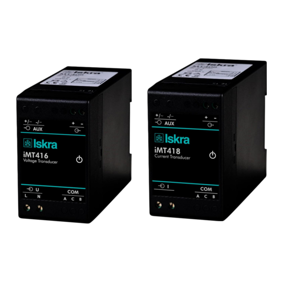
Page 33: Dimensions
TECHNICAL DATA Dimensions Construction Appearance Programmable AC measuring transducers iMT416/418 User’s Manual... - Page 34 Root Mean Square value TRMS True Root Mean Square value MODBUS Industrial protocol for data transmission MiQen Software for Iskra MIS instruments Alternating voltage, current Direct voltage, current Total harmonic distortion Measurement of average values in time interval (Maximum Demand) − Sample factor Defines a number of periods for measuring calculation on the basis of measured frequency −...
- Page 35 The tables below represent the complete set of MODBUS register map. VERSION 1 MODBUS Parameter Register Type Start Frequency 30105 30106 30107 30108 iMT416 30126 30127 iMT418 THD HARMONIC DATA U1 THD% 30182 iMT416 I1 THD% 30188 iMT418 Internal Temperature...
- Page 36 DEMAND VALUES DYNAMIC DEMAND VALUES 30175 30176 iMT418 MAX DEMAND SINCE LAST RESET 30207 30208 iMT418 All other MODBUS registers are a subject to change. For the latest MODBUS register definitions go to ISKRA MIS’s web page https://www.iskra.eu/en/. User’s Manual...
- Page 37 APPENDICES Data types decoding Type Bit mask Description Unsigned Value (16 bit) Example: 12345 = 3039(16) Signed Value (16 bit) Example: -12345 = CFC7(16) Signed Long Value (32 bit) Example: 123456789 = 075B CD 15(16) Short Unsigned float (16 bit) bits # 15…14 Decade Exponent(Unsigned 2 bit) bits # 13…00...
- Page 38 APPENDICES APPENDIX C: CALCULATIONS & EQUATIONS Calculations Definitions of symbols Symbol Definition Sample factor Average interval Phase voltage (U or U Total number of samples in a period Sample number (0 ≤ n ≤ N) Current sample n Phase voltage sample n User’s Manual...
- Page 39 APPENDICES EQUATIONS Voltage Phase voltage ∑ N − samples in one period (up to 65 Hz) = √ N − samples in M periods (above 65Hz) Example: 400 Hz → M Current Phase current ∑ = √ N − 128 samples in a period (up to 65 Hz) TRMS N −...
- Page 40 Published by Iskra, d.o.o. • Subject to change without notice • Version 1.00 July 2021 • EN K22.496.901...
Need help?
Do you have a question about the iMT416 and is the answer not in the manual?
Questions and answers