
Related Manuals for Iskra MT4 Series


Summary of Contents for Iskra MT4 Series
- Page 1 CONTENTSMT4xx MEASURING TRANSDUCER User’s Manual Measuring Transducer MT4xx Multifunction Transducer MT440 Voltage Transducer MT436 Current Transducer MT438 January 2017 • Version 2.00 User's Manual SR100 Supervision Relay...
- Page 2 This manual was produced using ComponentOne Doc-To-Help.™...
-
Page 3: Table Of Contents
CONTENTS Contents MT4xx MEASURING TRANSDUCER ................. 1 SECURITY ADVICE AND WARNINGS ................2 Warnings, information and notes regarding designation of the product ........ 3 Before switching the device on ....................3 Device switch-of Warning ......................4 Disposal ............................. 4 BASIC DESCRIPTION AND OPERATION ................5 Contents ............................ - Page 4 Contents Communication ........................20 Communication parameters (COM 1) ..................20 Modbus table ..........................20 USB Communication ........................21 Service USB Communication ...................... 21 Security............................ 21 Password-Level 0 >PL0) ......................21 Password-Level 1 >PL1) ......................21 Password-Level 2 >PL2) ......................21 A Backup Password->BP) ......................
- Page 5 Contents TEHNICAL DATA ......................34 Accuracy ..........................34 Inputs ............................35 Connection ..........................35 I/O modules ..........................36 Communication ........................37 Electronic features ........................37 Safety features ........................37 Mechanical ..........................38 Environmental conditions ....................... 38 Dimensions ..........................38 Connection table ........................39 APPENDICES .........................40 Appendix A ..........................
-
Page 7: Mt4Xx Measuring Transducer
MT4xx MEASURING TRANSDUCER MT4xx MEASURING TRANSDUCER MT440 MT436 MT438 User's Manual MT440/MT438/MT436 Measuring transducer... -
Page 8: Security Advice And Warnings
PLEASE NOTE ISKRA Company assumes no responsibility in connection with installation. This booklet contains instructions for installation and use of measuring instrument. Installation and use of a device also includes handling with dangerous currents and voltages therefore should be installed, operated, serviced and maintained by qualified persons only. If there is any doubt regarding installation and use of the system in which the device is used for measuring or supervision, please contact a person who is responsible for installation of such system. -
Page 9: Warnings, Information And Notes Regarding Designation Of The Product
SECURITY ADVICE AND WARNINGS Warnings, information and notes regarding designation of the product Used symbols: See product documentation. Double insulation in compliance with the EN 61010−1 standard. Functional ground potential. Note: This symbol is also used for marking a terminal for protective ground potential if it is used as a part of connection terminal or auxiliary supply terminals. -
Page 10: Device Switch-Of Warning
SECURITY ADVICE AND WARNINGS Device switch-of Warning Auxiliary supply circuits for (external) relays can include capacitors between supply and ground. In order to prevent electrical shock hazard, the capacitors should be discharged via external terminals after having completely disconnected auxiliary supply (both poles of any DC supply). Disposal It is strongly recommended that electrical and electronic equipment is not deposit as municipal waste. -
Page 11: Basic Description And Operation
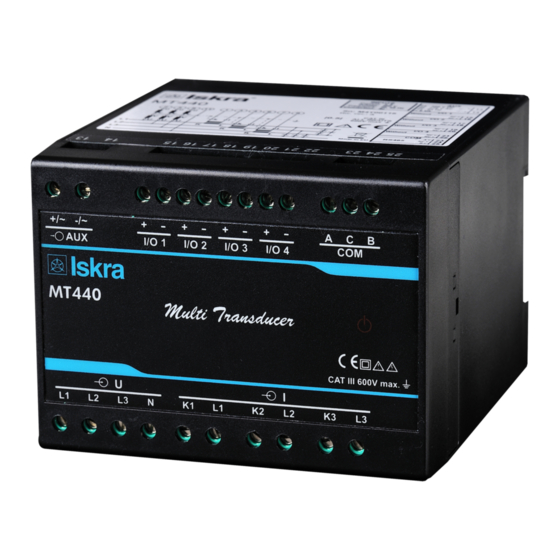
Fixation screws Short installation manual This document and settings software MiQen can also be found on our web page www.iskra.eu. CAUTION Please examine the equipment carefully for potential damages which might arise during transport! Description Measuring transducer is intended for measuring, analysing and monitoring single-phase or three-phase electrical power network. - Page 12 BASIC DESCRIPTION AND OPERATION Appearance Measuring transducer can differ from yours depending on the type and functionality. MT440 1 – Communication ports 2 – I/O modules 3 – Auxiliary supply 4 – Voltage inputs 5 – Current inputs 6 – Power ON LED MT436 1 –...
-
Page 13: Abbreviation/Glossary
Explanation Root Mean Square value MODBUS Industrial protocol for data transmission MiQen Setting Software for ISKRA instruments Alternating voltage PA total Angle calculated from total active and apparent power PA1, PA2, PA3 Angle between fundamental phase voltage and phase current... -
Page 14: Purpose And Use Of Different Type Of Measuring Transducer
BASIC DESCRIPTION AND OPERATION Purpose and use of different type of measuring transducer PLEASE NOTE Described in chapter below are main differences between different types of measuring transducers. Please note that in flowing chapters, these differences may not be specifically pointed out. Voltage transducer MT436 MT436 voltage transducer is intended for measuring and monitoring of single phase or three-phase electrical power network. - Page 15 BASIC DESCRIPTION AND OPERATION Supported measurements Basic measurements MT440 MT438 MT436 Phase Voltage U and U ● × ● Current I and I ● ● × Active power P , and P ● × × Reactive power Q , and Q ●...
-
Page 16: Connection
Connection shall therefore be performed ONLY a by a qualified person using an appropriate equipment. ISKRA, d.d. does not take any responsibility regarding the use and connection. If any doubt occurs regarding connection and use in the system which device is intended for, please contact a person who is responsible for such installations. -
Page 17: Mounting
CONNECTION Mounting MT4xx measuring transducer is designed for DIN rail mounting. It should be mounted on a 35 mm DIN rail by means of two plastic fasteners. Before installation fasteners should be in open position (pulled). After device is on place, fasteners are locked (pushed) to close position. - Page 18 CONNECTION System/connection Terminal assignment Connection 3b (1W3b) Three phase, three wire connection with balanced load Connection 3u (2W3u) Three phase, three wire connection with unbalanced load Connection 4b (1W4b) Three phase, four wire connection with balanced load Connection 4u (3W4u) Three phase, four...
-
Page 19: Connection Of Input/Output Modules
CONNECTION Voltage transducer MT436 System/ connection Terminal assignment Three phase, four wire connection Current transducer MT438 System/ connection Terminal assignment Three phase connection Connection of input/output modules WARNING Check the module features that are specified on the label, before connecting module contacts. Wrong connection can cause damage or destruction of module and/or device. -
Page 20: Communication Connection
RS485 RS485 communication is intended for connection of multiple devices to a network where devices with RS485 communication are connected to a common communication interface. We suggest using one of the ISKRA, d.d. communication interfaces! For proper operation it is necessary to assure the corresponding connection of individual terminals (see table: Survey of communication connection on page 15). -
Page 21: Survey Of Communication Connection
When MT4xx is connected to a PC through USB communication for the first time, a user is prompted to install a driver. The driver is automatically installed during MiQen software installation. MiQen software can be downloaded on Iskra, d.d. website (www.iskra.eu/download/software). With driver installed, USB is redirected to a serial port, which should be selected when using MiQen software. -
Page 22: Settings
PC. MiQen software MiQen software is a tool for a complete programming and monitoring of ISKRA measuring instruments. Remote operation is possible by means of serial (RS485/RS232) or USB communication (depending on device equipment). A user-friendly interface consists of six segments: Connection, Settings, Measurements, Analysis, My devices and Upgrades. -
Page 23: Setting Procedure
Upgrades In Upgrades section latest software, both for MiQen and ISKRA measuring devices can be found. The latest version should always be used to assure full functionality. Manual or automatic checking for upgrades is available. Internet connection is required. - Page 24 SETTINGS Temperature unit Choose a unit for temperature display. Degrees Celsius or degrees Fahrenheit are available. Maximum demand calculation (MD mode) The instrument provides maximum demand values using thermal function. A thermal function assures exponent thermal characteristic based on simulation of bimetal meters. Maximal values are stored in device. A time constant (t. c.) can be set from 1 to 255 minutes and is 6 −...
-
Page 25: Connection
SETTINGS Connection CAUTION Settings of connections shall reflect actual state otherwise measurements could not be valid. Connection mode When connection is selected, load connection and the supported measurements are defined. (see chapter Survey of supported measurements regarding Connection mode on page 28). Setting of current and voltage ratios Before setting current and voltage ratios it is necessary to be familiar with the conditions in which device will be used. -
Page 26: Communication
SETTINGS Communication Communication parameters (COM 1) MT4xx has one galvanically separated communication port, which can be equipped with RS232/RS485 or left open (to be specified with order). Different configurations are possible (to be specified with order): Configuration COM 1 RS232 USB + RS232 RS485 USB + RS485... -
Page 27: Usb Communication
>depending on a serial number of the device). The BP password is available in the user support department in ISKRA, d.d., and is entered instead of the password PL1 or/and PL2. Do not forget to state the device serial number when contacting the personnel in ISKRA, d.d. -
Page 28: Password Locks Time >Min)
SETTINGS Password locks time >min) Defines the time in minutes for the instrument to activate password protection. Enter value 0 if you want to use manual password activation. Password setting A password consists of four letters taken from the British alphabet from A to Z. When setting a password, only the letter being set is visible while others are hidden. -
Page 29: Inputs And Outputs
SETTINGS Inputs and outputs Module settings depend on built-in modules. Analogue output module Each of up to four analogue outputs is fully programmable and can be set to any of 6 full-scale ranges. Within each of those 6 ranges, other required output ranges can be set. For example, 4 … 20 mA range can be set when ± 20 mA full- scale range is selected: Output parameter Set the measured parameter to be transformed onto the analogue output. -
Page 30: Fast Analogue Output Module
SETTINGS Intrinsic-error (for analogue outputs) Defines the shape and up to 5 break points of an analogue output. For intrinsic-error for analogue outputs with bent or linear zoom characteristic multiply accuracy class with correction factor (c). Correction factor c (the highest value applies). -
Page 31: Relay Output Module
SETTINGS Relay output module Relay output module as well as Solid state output module can be assigned different functions. Alarm notification functionality (alarm output) Pulse output for energy measurement (pulse output) General purpose digital output (digital output) Pulse output functionality A corresponding energy counter (up to 4) can be assigned to a pulse output. -
Page 32: Alarms
Alarms Alarms are used for alarming exceeded set values of the measured quantities. Alarms setting MT440 supports setting up to 32 alarms in four alarm groups. Alarms can be set for any of measured parameters by setting condition and a limit value. A time constant of maximum demand values in a thermal mode, a delay time and switch-off hysteresis are defined for each group of alarms. -
Page 33: Measurements
MEASUREMENTS MT4xx are intended for measuring and monitoring single-phase or three-phase electrical power network. They measure true RMS value by means of fast sampling of voltage and current signals. Measurements (online) Online measurements are available with setting and monitoring software MiQen. Readings refresh rate of readings monitored with MiQen is fixed at approx. -
Page 34: Survey Of Supported Measurements Regarding Connection Mode
MEASUREMENTS Survey of supported measurements regarding connection mode Basic measurements Designat. Unit Phase Voltage U1 ● × × ● ● Voltage U2 × × × ○ ● Voltage U3 × × × ○ ● Average voltage U~ × × × ○... - Page 35 MEASUREMENTS Basic measurements Designat. Unit ● ● ○ ● Phase-to-phase voltage U12 × Phase- ● ● ○ ● to-phase Phase-to-phase voltage U23 × ● ● ○ ● Phase-to-phase voltage U31 × ● ● ○ ● Average phase-to-phase voltage (Uff) × ○...
-
Page 36: Explanation Of Basic Concepts
MEASUREMENTS Explanation of basic concepts Sample factor Mv A meter measures all primary quantities with sample frequency which cannot exceed a certain number of samples in a time period. Based on these limitations (128 sample/per at 65Hz) a sample factor is calculated. A sample factor (M depending on frequency of a measured signal, defines a number of periods for a measurement calculation and thus a number of harmonics considered in THD calculations. -
Page 37: Present Values
MEASUREMENTS Present values All measuring instruments may not support all the measurements. Please see chapter Purpose and use of different type of measuring transducer on page 8, for supported measurements. Voltage Instrument measures true RMS values of all phase voltages (U1, U2, U3), connected to the meter. Phase-to-phase voltages (U12, U23, U31), average phase voltage (Uf) and average phase-to-phase voltage (Ua) are calculated from measured phase voltages (U1, U2, U3). -
Page 38: Power Factor And Power Angle
MEASUREMENTS Power factor and power angle Power factor is calculated as quotient of active and apparent power for each phase separately (cos , cos , cos ) and total power angle (cos ). For correct display of PF via analogue output and application of the alarm, ePF (extended power factor) is applied. -
Page 39: Md Values
MEASUREMENTS MD values MD values and time stamp of occurrence are shown for: Three phase currents Active powers (import and export) Reactive power (ind. and cap.) Apparent power Dynamic demands are continuously calculated according to set time constants and other parameters. Reset demands are max. -
Page 40: Tehnical Data
TEHNICAL DATA TEHNICAL DATA In following chapter all technical data regarding operation of device is presented. Accuracy Total accuracy (measurements and analogue output) according to IEC/EN 60 688 is presented as percentage of range except when it is stated as an absolute value. Measured values Range Accuracy class... -
Page 41: Inputs
TEHNICAL DATA Inputs Voltage input Nominal range values 62.5, 125, 250, 500 V Nominal voltage(U 500 V Minimal measurement 2 V sinusoidal Frequency range 50/60, 400 Hz Max. measured value (cont.) 600 V ; 1000 V Max. allowed value 2 × U ;... -
Page 42: I/O Modules
TEHNICAL DATA I/O modules Electromechanical relay output module Purpose alarm, pulse, general purpose digital output Type Electromechanical Relay switch Rated voltage 48 V AC/DC (+40% max) Max. switching current 1000 mA Contact resistance ≤ 100 mΩ (100 mA, 24V) Pulse Max. -
Page 43: Communication
TEHNICAL DATA Communication Type RS232 RS485 Connection type Direct Network Direct Max. connection length 1000 m Number of bus stations ≤ 32 Connection terminals Screw terminals USB mini Insulation Protection class II, 3.3 kV 1 min Basic isolation only ACRMS Transfer mode Asynchronous Protocol... -
Page 44: Mechanical
TEHNICAL DATA Mechanical Dimensions W100 × H75× D105 mm Max. conductor cross section for terminals 2.5 mm with pin terminal 4 mm solid wire Vibration withstand 7 g, 3 … 100 Hz, 1 oct/min 10 cycles in each of three axes Shock withstand 300 g, 8 ms pulse 6 shocks in each of three axes... -
Page 45: Connection Table
TEHNICAL DATA Connection table Function Connection AC current (MT438) Measuring input AC voltage (MT436) + I/O 1 + I/O 2 Inputs / outputs + I/O 3 + I/O 4 + / AC (L) Auxiliary power supply –... -
Page 46: Appendices
APPENDICES APPENDICES Appendix A Modbus communication protocol Modbus is enabled via RS232 and RS485 or USB. The response is the same type as the request. Two versions of MODBUS register tables are available: VERSION 1: Compatibility with advanced family of transducers (MT500) ... - Page 47 APPENDICES MODBUS Parameter Register Type Start Reactive Power Total (Qt) 30148 30149 Reactive Power Phase L1 (Q1) 30150 30151 Reactive Power Phase L2 (Q2) 30152 30153 Reactive Power Phase L3 (Q3) 30154 30155 Apparent Power Total (St) 30156 30157 Apparent Power Phase L1 (S1) 30158 30159 Apparent Power Phase L2 (S2)
- Page 48 APPENDICES MODBUS Parameter Register Start Type DEMAND VALUES DYNAMIC DEMAND VALUES Time Into Period (minutes) 30501 30502 30503 30504 30505 30506 30507 Apparent Power Total (St) 30508 30509 Active Power Total (Pt) - (positive) 30510 30511 Active Power Total (Pt) - (negative) 30512 30513 Reactive Power Total (Qt) - L...
- Page 49 APPENDICES MODBUS 100% Parameter Register Type value Reactive Power Phase L3 (Q3) 30822 Reactive Power Total (Qt) 30823 Apparent Power Phase L1 (S1) 30824 Apparent Power Phase L2 (S2) 30825 Apparent Power Phase L3 (S3) 30826 Apparent Power Total (St) 30827 Power Factor Phase 1 (PF1) 30828...
- Page 50 APPENDICES MODBUS 100% Parameter Register Type value DYNAMIC DEMAND VALUES Active Power Total (Pt) - (positive) 30862 Active Power Total (Pt) - (negative) 30863 Reactive Power Total (Qt) - L 30864 Reactive Power Total (Qt) - C 30865 Apparent Power Total (St) 30866 30867 30868...
- Page 51 APPENDICES MODBUS Parameter Register Type Start Reactive Power Total (Qt) 30098 30099 Reactive Power Phase L1 (Q1) 30100 30101 Reactive Power Phase L2 (Q2) 30102 30103 Reactive Power Phase L3 (Q3) 30104 30105 Apparent Power Total (St) 30106 30107 Apparent Power Phase L1 (S1) 30108 30109 Apparent Power Phase L2 (S2)
- Page 52 APPENDICES MODBUS Parameter Register Type Start DEMAND VALUES DYNAMIC DEMAND VALUES Time Into Period (minutes) 30174 30175 30176 30177 30178 30179 30180 Apparent Power Total (St) 30181 30182 Active Power Total (Pt) - (positive) 30183 30184 Active Power Total (Pt) - (negative) 30185 30186 Reactive Power Total (Qt) - L...
- Page 53 Power Factor Total (PFt) 30831 All other MODBUS registers are a subject to change. For the latest MODBUS register definitions go to ISKRA’s web page www.ISKRA.eu. 100% values calculations for normalized measurements Un = (R40147 / R40146) * R30015 * R40149...
- Page 54 APPENDICES EXAMPLE of calculation using MODBUS registers and their data types: CT Primary = R40145 (Type T4) = 10^2 × 40 = 8028 −> 4000 A/10 = 400 A (16) CT Secondary = R40144 (Type T4) = 10^2 × 50 = 8032 −>...
- Page 55 APPENDICES Appendix B Calculations Definitions of symbols Symbol Definition Sample factor Average interval Phase voltage (U or U Phase-to-phase voltage (U or U Total number of samples in a period Sample number (0 ≤ n ≤ N) x, y Phase number (1, 2 or 3) Current sample n Phase voltage sample n Phase-to-phase voltage sample n...
- Page 56 APPENDICES Power Active power by phases N − a number of samples in a period n − sample number (0 ≤ n ≤ N) f − phase designation Phase-to-phase voltage −...
- Page 57 APPENDICES Current THD − value of first harmonic n − number of harmonic Phase voltage THD − value of first harmonic n − number of harmonic Phase-to-phase voltage THD ...
- Page 58 Printed in Slovenia • Subject to change without notice • GB K 22.496.520...
Need help?
Do you have a question about the MT4 Series and is the answer not in the manual?
Questions and answers