Table of Contents
Advertisement
Available languages
Available languages
Quick Links
Advertisement
Table of Contents

Related Manuals for U-Line H-1713


Summary of Contents for U-Line H-1713
- Page 1 Para Español, vea páginas 7-13. Pour le français, consulter les pages 14-20. H-1713, H-2770 1-800-295-5510 uline.com TAKE-A-NUMBER WIRELESS SYSTEM TOOLS NEEDED Large Flathead Screwdriver Mini Flathead Screwdriver Phillips Screwdriver PAGE 1 OF 20 0421 IH-1713...
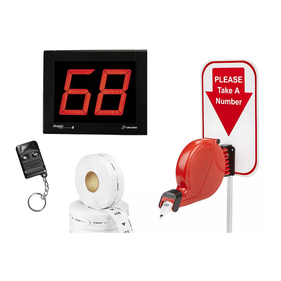
- Page 2 CONTENTS OF LARGE BOX (Wireless Push Button Set) (Display) Display Wall Mount Bracket x 1 Display x 1 Display x 1 (H-1713) (H-2770) Wireless Receiver x 1 Wireless Push Button x 2 Wall Anchor x 2 Large Phillips Screw x 2...
-
Page 3: Operation
OPERATION AND USE OF DISPENSER OPERATION NOTE: for permanent mounting, use the base of mounting stand as a template, mark and 1. Customer takes a number from the dispenser and drill four holes and secure base of stand to waits until the number appears on the display. surface with four screws (not included). -
Page 4: Electronic Display
DISPLAY – MOUNTING AND INSTALLATION ELECTRONIC DISPLAY 3. Attach 10 ft. power extension cable if necessary. (See Figure 10) MOUNTING BRACKET TO WALL 1. Determine where to place the display so it is easily seen by customers. 2. Mark mounting holes on wall using the display wall mount bracket as a template. - Page 5 DISPLAY – MOUNTING AND INSTALLATION CONTINUED SETUP OPTIONAL DISPLAY SETUP (See Figure 14) SETTING SOUND TONE AND VOLUME To enter setup options, make sure display is unplugged. Hold down (+) on the wireless push button and plug the Use a mini flathead screwdriver to change the tone and display back in.
- Page 6 PROGRAMMING WIRELESS PUSH BUTTON NOTE: The wireless push button codes must be 3. Press #2 on the wireless receiver and hold for three copied to the wireless receiver. The maximum seconds. The red LED light on the back of the wireless number of wireless push buttons per wireless receiver will start blinking.
-
Page 7: Herramientas Necesarias
H-1713, H-2770 800-295-5510 uline.mx SISTEMA TOMATURNOS INALÁMBRICO HERRAMIENTAS NECESARIAS Desarmador Grande de Cabeza Plana Minidesarmador de Cabeza Plana Desarmador de Cruz PAGE 7 OF 20 0421 IH-1713... - Page 8 CONTENIDO DE LA CAJA PEQUEÑA (Set del Botón Pulsador Inalámbrico) 1 Soporte de Montaje en Pared para la Pantalla 1 Pantalla 1 Pantalla (H-2770) (H-1713) 2 Botones Pulsadores 2 Taquetes 2 Tornillos de Cruz Grandes Inalámbricos 1 Receptor Inalámbrico NOTA: El control remoto CONTENIDO DE LA BOLSA GRANDE inalámbrico adicional en...
- Page 9 FUNCIONAMIENTO Y USO DEL DESPACHADOR FUNCIONAMIENTO NOTA: Para un montaje permanente, utilice la placa de la base de montaje como plantilla, 1. El cliente toma un número del despachador y espera marque y taladre cuatro orificios y fije la hasta que el número aparece en la pantalla. placa de la base a la superficie con cuatro 2.
- Page 10 PANTALLA - MONTAJE E INSTALACIÓN PANATALLA ELECTRÓNICA 3. Si fuera necesario, conecte la extensión del cable de electricidad de 10 pies. (Vea Diagrama 10) MONTAJE DEL SOPORTE EN LA PARED 1. Determine dónde colocar la pantalla de forma que los clientes puedan verla con facilidad. 2.
- Page 11 CONTINUACIÓN DE PANTALLA - MONTAJE E INSTALACIÓN CONFIGURACIÓN ENCENDER LA PANTALLA La pantalla muestra una serie de mensajes mientras se CONFIGURAR EL TONO Y VOLUMEN DEL SONIDO enciende una vez que se conecta. (Vea Diagrama 13) Use un minidesarmador para cambiar los interruptores La pantalla muestra: de tono y volumen ubicados en la parte posterior de la pantalla.
- Page 12 CONTINUACIÓN DE PANTALLA - MONTAJE E INSTALACIÓN CONFIGURACIÓN OPCIONAL DE LA PANTALLA 3. Configurar lel parpadeo de la pantalla cuando el número cambia: (Vea Diagrama 14) • La pantalla muestra la palabra "FL" seguida de Para accesar a las opciones de configuración, la configuración actual mostrando el número de asegúrese que la pantalla esté...
- Page 13 PROGRAMAR EL BOTÓN PULSADOR INALÁMBRICO NOTA: Los códigos del botón pulsador 3. Presione #2 en el receptor inalámbrico y sostenga inalámbrico deben ser transferidos al receptor por tres segundos. La luz roja LED en la parte trasera inalámbrico. El número máximo de botones del receptor inalámbrico comenzará...
-
Page 14: Outils Requis
H-1713, H-2770 1-800-295-5510 uline.ca SYSTÈME « PRENEZ UN NUMÉRO » – SANS FIL OUTILS REQUIS Grand tournevis à tête plate Mini tournevis à tête plate Tournevis cruciforme PAGE 14 OF 20 0421 IH-1713... - Page 15 (Ensemble de boutons-poussoirs sans fil) (Affichage) Support de fixation murale de l'indicateur x 1 Indicateur x 1 Indicateur x 1 (H-1713) (H-2770) Bouton-poussoir sans fil x 2 Récepteur sans fil x 1 Longues vis cruciformes x 2 Ancrages muraux x 2 REMARQUE : La télécommande de...
-
Page 16: Fixation Murale
FONCTIONNEMENT ET UTILISATION DU DISTRIBUTEUR FONCTIONNEMENT REMARQUE : pour installer le pied de façon permanente, marquez et percez quatre 1. Le client saisit un billet du distributeur et attend que trous en utilisant la base du pied de fixation son numéro s'affiche sur l'indicateur. comme guide, puis fixez et sécurisez la base du pied à... - Page 17 INDICATEUR – MONTAGE ET INSTALLATION INDICATEUR ÉLECTRONIQUE 3. Si nécessaire, raccordez la rallonge d'alimentation de 10 pi. (Voir Figure 10) FIXER LE SUPPORT AU MUR 1. Déterminez où installer l'indicateur afin qu'il puisse être vu facilement par les clients. 2. Marquez les trous de fixation sur le mur en utilisant le support de fixation murale de l'indicateur comme Câble d'alimentation Rallonge...
- Page 18 INDICATEUR – MONTAGE ET INSTALLATION SUITE CONFIGURATION DÉMARRAGE DE L'INDICATEUR Au démarrage, l'indicateur affiche un certain nombre RÉGLAGE DE LA TONALITÉ ET DU VOLUME de messages lorsqu'il est branché. (Voir Figure 13) Utilisez un mini tournevis pour changer les commutateurs L'indicateur affiche : de tonalité...
- Page 19 INDICATEUR – MONTAGE ET INSTALLATION SUITE RÉGLAGE OPTIONNEL DE L'INDICATEUR 3. Réglez le clignotement de l'indicateur lors d'un (Voir Figure 14) changement de numéro : Pour accéder aux options de réglage, rassurez-vous que • L'indicateur affiche « FL » suivi du réglage actuel du l'indicateur est débranché.
- Page 20 CONFIGURATION DE LA TÉLÉCOMMANDE SANS FIL REMARQUE : Les codes de bouton-poussoir sans 3. Appuyez sur le bouton nº 2 du récepteur sans fil et fil doivent être enregistrés au récepteur sans fil. maintenez-le enfoncé pendant trois secondes. Le Le nombre maximum de boutons-poussoirs sans voyant DEL rouge à...
Need help?
Do you have a question about the H-1713 and is the answer not in the manual?
Questions and answers