Advertisement
Available languages
Available languages
Quick Links
π
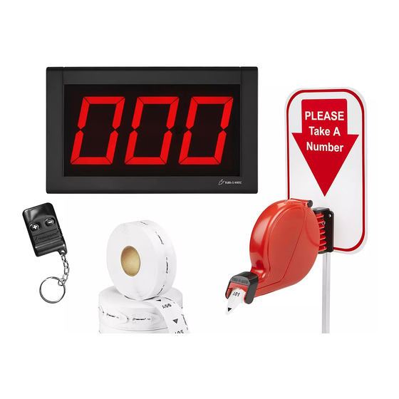
H-2770
3-DIGIT
TAKE-A-NUMBER
WIRELESS SYSTEM
PAGE 1 OF 20
1-800-295-5510
uline.com
Pour le français, consulter les pages 14-20.
TOOLS NEEDED
Large Flat Head Screwdriver
Mini Flat Head Screwdriver
Phillips Screwdriver
Para Español, vea páginas 7-13.
1015 IH-2770
Advertisement

Related Manuals for U-Line H-2770


Summary of Contents for U-Line H-2770
- Page 1 Para Español, vea páginas 7-13. Pour le français, consulter les pages 14-20. π H-2770 1-800-295-5510 uline.com 3-DIGIT TAKE-A-NUMBER WIRELESS SYSTEM TOOLS NEEDED Large Flat Head Screwdriver Mini Flat Head Screwdriver Phillips Screwdriver PAGE 1 OF 20 1015 IH-2770...
- Page 2 PARTS COUNT PIECES BEFORE ASSEMBLING CONTENTS OF MEDIUM BOX INSIDE THE DISPENSER (The Dispenser) Large Slotted Screws x 3 Large Slotted Bolts x 2 Dispenser Mounting Bracket x 1 Nuts x 2 Dispenser x 1 "Please Take A Number" Sign x 1 Label Sheet x 1 CONTENTS OF LARGE BOX (Display)
- Page 3 OPERATION OPERATION FOR PERMANENT MOUNTING: Using the base of Mounting Stand as a template, mark and drill 4 1. Customer takes a number from the Dispenser and holes and secure base of stand to surface with 4 waits until the number appears on the Indicator. screws (not included).
- Page 4 INDICATOR - MOUNTING AND INSTALLATION ELECTRONIC INDICATOR 2. Choose correct country outlet adapter for AC plug-in. (See Figure 9) MOUNTING BRACKET TO WALL 1. Determine where to place the Indicator so it is easily Adapter seen by customers. AC Plug-in 2.
- Page 5 INDICATOR - MOUNTING AND INSTALLATION CONTINUED SET-UP INDICATOR SET-UP (See Figure 14) Restart the Indicator by unplugging it and plugging it SETTING SOUND TONE AND VOLUME back in. Hold down (+) on the wireless push button while Use a mini screwdriver to change the tone and volume the Indicator Start-up displays "RUN"...
- Page 6 PROGRAMMING WIRELESS REMOTE NOTE: The wireless push button codes must be 3. Press B on the wireless receiver and hold for three copied to the wireless receiver. The maximum seconds. The red LED light on the back of the wireless number of wireless push buttons per wireless receiver will start blinking.
-
Page 7: Herramientas Necesarias
π H-2770 01-800-295-5510 uline.mx SISTEMA TOMATURNOS INALÁMBRICO DE 3 DÍGITOS HERRAMIENTAS NECESARIAS Desarmador de Cabeza Plana Grande Mini Desarmador de Cabeza Plana Desarmador de Cruz PAGE 7 OF 20 1015 IH-2770... - Page 8 PARTES CUENTE LAS PIEZAS ANTES DE ENSAMBLAR DENTRO DEL DESPACHADOR CONTENIDO DE LA CAJA MEDIANA (El Despachador) 3 Tornillos Ranurados Grandes 2 Pernos Ranurados Grandes 1 Soporte de Montaje para 2 Tuercas Despachador 1 Despachador 1 Letrero "Please Take A Number" 1 Hoja de Etiquetas (Por favor, tome un número) CONTENIDO DE LA CAJA GRANDE...
- Page 9 FUNCIONAMIENTO FUNCIONAMIENTO PARA UN MONTAJE PERMANENTE: Usando la base del soporte de montaje como plantilla, marque y 1. El cliente toma un número del despachador y espera taladre 4 orificios y asegure la base del soporte a hasta que el número aparece en el indicador. la superficie con 4 tornillos (no incluidos).
- Page 10 INDICADOR - MONTAJE E INSTALACIÓN INDICADOR ELECTRÓNICO 3. Si fuera necesario, conecte la extensión del cable de electricidad de 10 pies. (Vea Diagrama 10) MONTAJE DEL SOPORTE EN LA PARED 1. Determine dónde colocar el indicador de forma que los clientes puedan verlo con facilidad. 2.
- Page 11 CONTINUACIÓN DE INDICADOR - MONTAJE E INSTALACIÓN CONFIGURACIÓN ENCENDER EL INDICADOR El indicador muestra una serie de mensajes mientras se CONFIGURAR EL TONO Y VOLUMEN DEL SONIDO enciende una vez que se. (Vea Diagrama 13) Use un destornillador mini para cambiar los interruptores La pantalla muestra: de tono y volumen ubicados en la parte posterior del indicador.
- Page 12 CONTINUACIÓN DE INDICADOR - MONTAJE E INSTALACIÓN CONFIGURACIÓN DEL INDICADOR 3. El indicador fijo parpadea cuando el número (Vea Diagrama 14) cambia: Reinicie el indicador desenchufándolo y volviéndolo • El indicador muestra la palabra 'FL' seguida de a enchufar. Mantenga presionado el símbolo (+) en el la configuración actual mostrando el número de botón pulsador inalámbrico mientras en el encendido parpadeos.
- Page 13 PROGRAMAR EL CONTROL REMOTO NOTA: Los códigos del botón pulsador 3. Presione B en el receptor inalámbrico y sostenga por inalámbrico deben ser transferidos al receptor tres segundos. La luz roja LED en la parte trasera del inalámbrico. El número máximo de botones receptor inalámbrico comenzará...
-
Page 14: Outils Requis
π H-2770 1-800-295-5510 uline.ca SYSTÈME « PRENEZ UN NUMÉRO » À 3 CHIFFRES – SANS FIL OUTILS REQUIS Grand tournevis à tête plate Mini tournevis à tête plate Tournevis cruciforme PAGE 14 OF 20 1015 IH-2770... - Page 15 PIÈCES COMPTEZ LES PIÈCES AVANT D'ASSEMBLER ARRÊT ARRÊT CONTENU DE LA BOÎTE MOYENNE INTÉRIEUR DU DISTRIBUTEUR (Le distributeur) Longues vis fendues x 3 Long boulon à encoche Support de fixation du Écrous x 2 distributeur x 1 Distributeur x 1 Enseigne « Please Take A Number »...
- Page 16 FONCTIONNEMENT FONCTIONNEMENT POUR INSTALLER LE PIED DE FAÇON PERMANENTE : Marquez et percez quatre trous en utilisant le pied 1. Le client saisit un billet du distributeur et attend que de fixation comme guide, puis fixez et sécurisez la son numéro s'affiche sur l'indicateur. base du pied à...
- Page 17 INDICATEUR – MONTAGE ET INSTALLATION INDICATEUR ÉLECTRONIQUE 3. Si nécessaire, raccordez la rallonge d'alimentation de 3 m (10 pi). (Voir Figure 10) FIXER LE SUPPORT AU MUR 1. Déterminez où installer l'indicateur afin qu'il puisse être vu facilement par les clients. 2.
- Page 18 INDICATEUR – MONTAGE ET INSTALLATION SUITE CONFIGURATION DÉMARRAGE DE L'INDICATEUR Au démarrage, l'indicateur affiche un certain nombre RÉGLAGE DE LA TONALITÉ ET DU VOLUME de messages lorsqu'il est branché. (Voir Figure 11) Utilisez un mini tournevis pour changer les commutateurs L'indicateur affiche : de tonalité...
- Page 19 INDICATEUR – MONTAGE ET INSTALLATION SUITE RÉGLAGE DE L'INDICATEUR 3. Réglez le clignotement de l'indicateur lors d'un (Voir Figure 14) changement de numéro : Redémarrez l'indicateur en le débranchant et en le • L'indicateur affiche « FL » suivi du réglage actuel du rebranchant.
- Page 20 CONFIGURATION DE LA TÉLÉCOMMANDE SANS FIL REMARQUE : Les codes de bouton-poussoir sans 3. Appuyez sur le bouton « B » du récepteur sans fil fil doivent être enregistrés au récepteur sans fil. et maintenez-le enfoncé pendant 3 secondes. Le Le nombre maximum de boutons-poussoirs sans voyant DEL rouge à...
Need help?
Do you have a question about the H-2770 and is the answer not in the manual?
Questions and answers