
Related Manuals for Carbolite Gero GPCMA 174


Summary of Contents for Carbolite Gero GPCMA 174
- Page 1 Installation and Operation Instructions 1000-1150°C Retort Chamber Furnace Model: GPCMA 174 litres GPCMA 174 MEN-GPCMA174-IO (07-07-2021)
-
Page 2: Table Of Contents
Contents This manual is for guidance on the use of the Carbolite Gero product specified on the front cover. This manual should be read thoroughly before unpacking and using the furnace or oven. The model details and serial number are shown on the back of this manual. - Page 3 Automatic Vacuum Option (if fitted) 7.0 Installation Manual Handling Unpacking Siting and Setting Up 7.4 Water-Cooled Door Seal Connections 7.5 Gas Connections 7.6 Electrical Connections 7.6.1 1-Phase Connections 7.6.2 3-Phase Connections 7.7 Retort Thermocouple Installation 8.0 Temperature Controller 9.0 Commissioning Pre-Commissioning Commissioning - Initial Function Checks 10.0 Operation...
- Page 4 13.0 Decommissioning, Storage and Disposal 13.1 Decommissioning 13.2 Storage (Long Term) 13.3 Disposal...
-
Page 5: Introduction
Gero for additional assistance. Note: If this product is used for any application other than its intended purpose, as stated by Carbolite Gero, the protection provided by this equipment may be impaired. Note: Failure to comply with the instructions as stated within this manual will constitute misuse and subsequently void any warranty provided by Carbolite Gero. - Page 6 The customer must provide an adequate ventilation and fume extraction system to manage any fumes given off by materials during processing The customer is responsible for providing and maintaining the connections for the electrical power supply, inert gas supply, and cooling water supply and drain. The furnace should not be operated until all required supplies are connected.
-
Page 7: Prerequisites To Use
1.2 Prerequisites to Use Prior to the commissioning and use of this product, all personnel involved in its installation, operation and maintenance must be deemed competent and have: Read and understood the information contained within this manual Received the relevant training with regard to safety and operation of the product Been provided with the appropriate PPE (Personal Protective Equipment) required for the safe operation of this product Note: The customer is responsible for ensuring that all of the above conditions are... -
Page 8: Safety
2.0 Safety Symbols and Warnings Note: Observe and take the appropriate precautions if any of the following warning symbols are displayed on this product or in your working environment. Refer to the instruction Disconnect the product manual before from the power supply operating or before performing any maintaining the... -
Page 9: Operator Safety
Note: It is the responsibility of the customer to ensure that all personnel required to operate this product are fully trained and equipped with the appropriate PPE (Personal Protective Equipment). Carbolite Gero recommend that the appropriate PPE is worn at all times whilst working with and around this product. -
Page 10: Risk Prevention And Mitigating Residual Risks
Avoid breaking up insulation material hazardous Please refer to section 2.4 for further details material If in doubt, please contact Carbolite Gero Service Safety Warning - Refractory Fibre Insulation Insulation made from High Temperature Insulation Wool Refractory Ceramic Fibre, better known as (Alumina silicate wool - ASW). - Page 11 Further information can be provided on request. Alternatively, Carbolite Gero Service can quote for any repairs to be carried out either on site or at the Carbolite Gero factory.
-
Page 12: Product Overview
The product rating label is located on the side of the product control box. Note: The image below is an example and does not reflect the product(s) covered by this manual. UKCA Mark Carbolite Gero address and website CE Mark Country of Origin Product Model... -
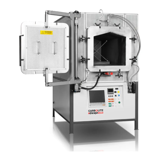
Page 13: Part Identification
3.2 Part Identification Note: Some models may have additional options and features that are not represented by the following images. Actuated Damper Valve (Forced Cooling option) Chimney Oxygen Sensor (Lambda Sensor) Retort pressure relief valve Retort cooling water inlet/outlet Door gear assembly Retort door Retort securing nuts Electrical door interlock... -
Page 14: Dimensions
Dimensions Height of furnace Width of furnace Depth of furnace Width of control panel Height of control panel Clearance below control panel Width of unit (door closed) Width of unit (maximum with door open) Depth of unit (from pivot point to fur- nace back panel) Height from floor to base of retort Depth of retort (internal) - Page 15 Note: All dimensions are measured in millimetres (mm). 1976 1107 1869 316 600 1258 1520 2490 1538 1042 820 500 1113 * These dimensions may change depending on the controller options ordered. Please refer to the separate product documentation pack for details relevant to your furnace. ** For models ordered with vacuum retorts, this dimension will be smaller than specified in this table.
-
Page 16: Specifications
4.0 Specifications Furnace Retort Material 1000 310 Stainless Steel 1050 314 Stainless Steel Maximum Temperature (°C) 1100 Inconel 601 1150 Haynes 230 310 Stainless Steel 314 Stainless Steel Maximum Continuous Operating Temperature (°C) 1000 Inconel 601 1050 Haynes 230 Note: Please refer to the separate product documentation pack for additional specifications relevant to your product. -
Page 17: Electrical Specifications
5.0 Electrical Specifications This equipment MUST be earthed! Fuses and Power Settings Please refer to the supplementary electrical information in the product document pack provided with this product. Operating / Storage Environment The products covered by this manual contain electrical parts and should be stored and used in indoor conditions as follows: Temperature: 5°C - 40°C... -
Page 18: Options And Accessories
6.0 Options and Accessories Note: Any additional equipment to be used with this product should be supplied by Carbolite Gero. Accessories from third-party sources are not designed to Carbolite Gero's specifications and may result in poor performance, damage to equipment or dangerous working conditions. -
Page 19: Loading Trolley Option
Loading Trolley Option The GPCMA is available with an optional trolley to aid the operator with the loading and unloading of samples. The sample(s)/sample carrier is supported on the loading trolley forks, which are then raised or lowered by turning the handle located at the rear of the trolley. -
Page 20: Electrical Door Interlock (If Fitted)
6.3 Electrical Door Interlock (if fitted) Note: To open the door, the electrical supply to the product must be switched on! The electrical door interlock is situated on the underside of the retort door. It is linked to a relay within the main temperature controller and can be configured to operate based on a temperature limit. -
Page 21: Gas System Options
6.4 Gas System Options The GPCMA is available with a choice of gas system and flowmeter options. The flow of gas is always turned on and off by program segment events within the temperature controller/ programmer, regardless of gas system option. 6.4.1 Semi-Automatic Gas System with Analogue Flowmeters - Nitrogen/ Argon Gas flow rates are required to be set manually via needle valves, but gas flow is turned... -
Page 22: Gas Flow Rates
6.5 Gas Flow Rates The GPCMA gas system includes two gas flow rates, purge (high) and process (low): The purge flow rate is used initially to reduce oxygen levels within the retort cham- ber and create an inert gas atmosphere. The process flow rate is used during heating to maintain the atmosphere within the retort chamber. -
Page 24: Chiller Option (If Fitted)
6.7 Chiller Option (if fitted) 6.7.1 Water Connections If the furnace has been ordered with an optional chiller, then the cooling water supply and drain lines must be connected between the free-standing chiller and the furnace cabinet. Water connections are supplied connected to the retort and ready to operate (see section 7.4). -
Page 25: Installation
7.0 Installation Manual Handling Refer to section3.2 of this manual for product dimensions. Mechanical lifting equipment may be necessary! Consult personnel responsible for health and safety before attempting to move this product! It is the responsibility of the customer to provide any mechanical lifting aids, such as pallet trucks, forklifts or cranes, and to ensure that all operators of such equipment are fully trained and qualified. -
Page 26: Siting And Setting Up
The height of the mounting surface is important to avoid operator strain when loading and unloading samples. An optional custom loading trolley is available. Please contact Carbolite Gero for details. Unless otherwise stated elsewhere in this manual, ensure that there is at least 1000 mm of free space around the back and at least 500mm of free space at the sides of the product. - Page 27 * Note: Please refer to section 3.2. Adequate space must be provided to accommodate the furnace with the door open. Note: Depending on the application of the product, it may be appropriate to position it under an extraction hood. Ensure the extraction hood is switched on during use.
-
Page 28: Water-Cooled Door Seal Connections
7.4 Water-Cooled Door Seal Connections The furnace has a silicone rubber door seal protected by a water-cooling system that runs around the back of the furnace door. Water inlet and outlet pipes are situated at the top of the door and connect to inlets and outlets on the top of the furnace. The main water supply inlet and outlets are situated at the rear of the furnace beside... -
Page 29: Gas Connections
7.5 Gas Connections Note: The furnace retort is not designed to operate as a pressure vessel, and is fitted with a pressure relief valve at the exhaust. To mitigate the risk of pressure build up, before each use, check that the retort exhaust pipe is free of any obstructions e.g. -
Page 30: Electrical Connections
7.6 Electrical Connections For products supplied without pre-fitted plugs, it is recommended that all electrical connections are carried out by a qualified electrician. The product covered by this manual normally requires a single phase A.C. supply, which may be "Live to Neutral non-reversible", "Live to Neutral reversible" or "Live to Live". -
Page 31: 3-Phase Connections
7.6.2 3-Phase Connections Terminal Label Cable Colour Connection Black to phase 1 Black to phase 2 Black to phase 3 Light Blue to neutral (if fitted) Green / Yellow to earth (ground) -
Page 32: Retort Thermocouple Installation
7.7 Retort Thermocouple Installation Probe thermocouples enable operators to record more accurate temperature readings inside a heated vessel (work tube, retort, reactor etc.). The thermocouples enter the retort through compression glands, and plug into the corresponding sockets on the rear of the furnace case. Thermocouples may also be plugged into an independent external temperature reader. -
Page 33: Temperature Controller
8.0 Temperature Controller Please refer to the separate temperature controller manual(s) provided. -
Page 34: Commissioning
Note: This equipment should not be put into use until it has been commissioned by a competent person in accordance with the instructions contained within this manual, and any local regulations. Carbolite Gero offer an installation and commissioning service. Please contact Carbolite Gero Service for details. -
Page 35: Commissioning - Initial Function Checks
Check that an earth connection has been made. Earth Connection The retort and all removable panels should be earthed. Check that all connections between the equipment have been made as detailed in this manual: Gas Connections Gas supply to furnace Gas supply to retort Check that the required thermocouples are Thermocouples... -
Page 36: Operation
Please contact Carbolite Gero to request the "Maintenance" manual for your product. Note: DO NOT leave the product operating unattended unless the over- temperature protection option is fitted. -
Page 37: Basic Operating Cycle
The door is secured using 8 manual screw bolts, and features an electrical interlock which prevents the door from being opened while the furnace is in operation. To access the furnace chamber: Unscrew the door bolts and flip them back away from the door. Whilst holding both front handles, gently pull the door directly outwards, taking care to avoid the door plug making contact with the inside of the retort chamber. -
Page 38: Vacuum Operation And Process Gas Control (If Fitted)
10.4 Vacuum Operation and Process Gas Control (if fitted) Both the vacuum (if fitted) and gas systems are controlled by the temperature controller/ programmer. Vacuum and process gas injections can only be operated via program segment events within a temperature program. Automatic valves control the exhaust gas flow, sending it either via the vacuum pump or directly to the exhaust chimney. - Page 39 In each program segment within the temperature controller/ programmer, there are four "Events" that may be activated: Event 1 starts the vacuum pump Event 2 turns on the purge (high) gas flow rate (flow rate 1) Event 3 controls the process (low) gas flow rate (flow rate 2) Event 4 starts the forced cooling system (if fitted) Note: Event 1 cannot be active when either Event 2 and/ or Event 3 are active.
-
Page 40: Use Of Probes And Metal Sheathed Thermocouples
10.5 Use of Probes and Metal Sheathed Thermocouples Any metal object used to probe into the product chamber while the product is connected to the electrical supply must be earthed. This applies in particular to metal sheathed thermocouples, where the sheaths must be earthed. -
Page 41: Maintenance
11.0 Maintenance 11.1 General Maintenance Preventive rather than reactive maintenance is recommended. The type and frequency depends on the product use; the following are recommended. 11.2 Maintenance Schedule CUSTOMER QUALIFIED PERSONNEL DANGER! ELECTRIC SHOCK. Risk of fatal injury. Only electrically qualified personnel should attempt these maintenance procedures. - Page 42 Function Tested using certified equipment, fre- Temperature Cal- quency dependent on the standard ibration required Check that all functions are working nor- Operational Check mally Thorough inspection and report incor- Operational Check porating a test of all functions Performance Element Circuit Electrical measurement Measure the current drawn on each Power Consumption...
-
Page 43: Cleaning
Open the door and check the heater lights. They should no longer be illuminated. If the heater lights remain illuminated when the door is open, discontinue use and contact Carbolite Gero Service. Annual check: The following checks should be carried out by a qualified electrician, as specified in the "Maintenance Schedule"... -
Page 44: Calibration
11.7 Recommended Spare Parts and Spare Parts Kit Carbolite Gero can supply individual spare parts or a kit of the items most likely to be required. Ordering a kit in advance can save time in the event of a breakdown. -
Page 45: Fault Analysis
12.0 Fault Analysis Furnace Does Not Heat Up The HEAT The heating element Check also that the SSR is light is ON has failed working correctly The HEAT The controller shows a The thermocouple has broken or light is very high temperature has a wiring fault or code such as S.br The controller shows a... -
Page 46: Product Overheats
Product Overheats Product only heats The controller up when the shows a very high The controller is faulty instrument switch is temperature The thermocouple may be The controller faulty or may have been shows a low removed out of the heating temperature chamber The thermocouple may be... - Page 47 Within the European Community the disposal of electrically operated devices is regulated according to guidance based on the EU Directive 2012/19/EU on Waste Electrical and Electronic Equipment (WEEE). Disposal regulations may differ worldwide. If uncertain, please contact Carbolite Gero for advice on disposal.
- Page 49 Notes Service Record Engineer Name Date Record of Work...
- Page 50 The products covered in this manual are only a small part of the wide range of ovens, chamber furnaces and tube furnaces manufactured by Carbolite Gero for laboratory and industrial use. For further details of our standard or custom built products please contact us at the address below, or ask your nearest stockist.
Need help?
Do you have a question about the GPCMA 174 and is the answer not in the manual?
Questions and answers