
Related Manuals for Carbolite Gero HTF 17/10


Summary of Contents for Carbolite Gero HTF 17/10
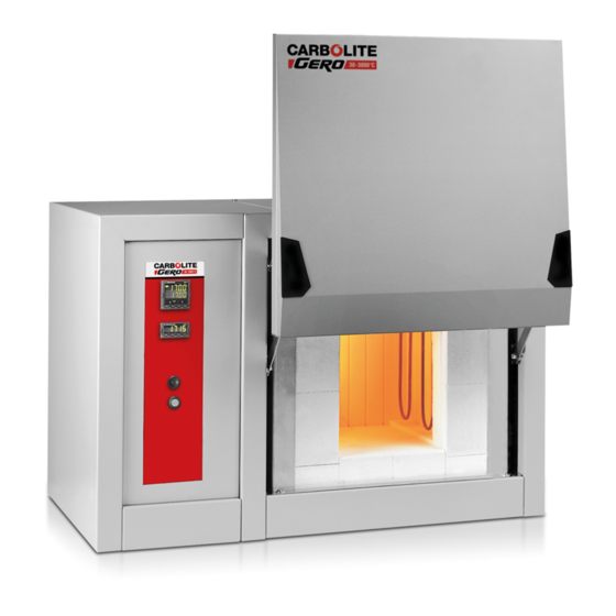
- Page 1 Installation, Operation and Maintenance Instructions 1700 °C Chamber Furnace - HTF: 10 Litres 3216 Controller HTF 17/10 + 3216 Controller MEN-HTF1710-002_3216_V01...
-
Page 2: Table Of Contents
Contents This manual is for guidance on the use of the Carbolite Gero product specified on the front cover. This manual should be read thoroughly before unpacking and using the furnace or oven. The model details and serial number are shown on the back of this manual. - Page 3 3.7.5 Holdback 3.7.6 Ramp Rate 3.7.7 Target Setpoint 3.7.8 Dwell Time 3.7.9 Running a Program 3.7.10 Program Status 3.7.11 Process Value 3.7.12 PSP, Segment Type and Number Controller Options 3.8.1 Digital Communications - RS232 3.8.2 Digital Communications - RS485 3.8.3 Comms Address 3.8.4 Alarm Option...
- Page 4 5.12 General Operating Advice 6.0 Maintenance General Maintenance 6.1.1 Cleaning 6.1.2 Safety Switch 6.1.3 Other Electrical Components 6.1.4 Element Glaze Calibration After-Sales Service Recommended Spare Parts and Spare Parts Kit Power Adjustment (Controller) Power Adjustment (Thyristor) Low Voltage Compensation 7.0 Repairs and Replacements Safety Warning - Disconnection from Power Supply Safety Warning - Refractory Fibre Insulation Side Panel Removal...
-
Page 5: 1.0 Symbols And Warnings
1.0 Symbols and Warnings 1.0 Symbols and Warnings Switches and Lights Instrument switch: when the instrument switch is operated the temperature control circuit is energised. Heat light: the adjacent light glows or flashes to indicate that power is being supplied to the elements. Warning Symbols DANGER –... - Page 6 1.0 Symbols and Warnings Caution – Double Pole/Neutral Fusing...
-
Page 7: 2.0 Installation
2.0 Installation 2.0 Installation Unpacking and Handling When unpacking or moving the product always lift it by its base. Do not use the door or any other protruding parts. The product contains a transformer and is heavy: use two or more people to carry the product. Remove any packing material from the door great and from inside the product chamber. -
Page 8: Electrical Connections
2.0 Installation Separately Packed Items 1700 °C Models Elements Element Clamps Element Clips Braids 1 set of 5 Separators/ Block Chimney Unit The installation of these elements is described in section 7.8 Electrical Connections Connection by a qualified electrician is recommended. These models are designed only for single phase electrical supplies, or for two live phases and neutral of a 3-phase supply. -
Page 9: Power Supply Notes
2.0 Installation Electrical Connection Details: Supply Types Supply Terminal Label Cable Colour Reversible or Live- Live - Neutral Live to either power 1-phase L Brown to live conductor to the other power Blue to neutral conductor Green/ Yellow to earth to earth (ground) (ground) 2-phase L1... - Page 10 220 V to 230 V: move a cable to the 230 V, and adjust the thyristor stack. Please contract Carbolite Gero Service for guidance and assistance if the power supply shown on the rating label does not match the power supply available.
-
Page 11: 3.0 3216 Controller
3.0 3216 Controller 3.0 3216 Controller PID control This controller uses PID (Proportional Integral Derivative) temperature control. This type of control uses a complex mathematical control system to adjust the heating power and achieve the desired temperature. 3216P1 The 3216P1 is a digital temperature controller which uses PID algorithms to give excellent temperature control. -
Page 12: Keys
3.0 3216 Controller 3.4.2 Keys The page key is used to access level 2 when held down Page Key for 3 seconds. Scroll Key The scroll key is used to scroll through parameters. When pressed simultaneously the ACK function is used Page and Return to the Home Menu Scroll... -
Page 13: Using The Controller
3.0 3216 Controller 3.5.3 Using the Controller The parameters in the controller are first shown by a short code (mnemonic). After 5 Seconds a description of the parameter will scroll once along the display and then revert back to the mnemonic. The scrolling text can be interrupted at any time by a single press of any of the buttons, but will not scroll again until the parameter is returned to. -
Page 14: Setting Up The Controller
3.0 3216 Controller Alarms (if configured) Current Transformer Input (if configured) Comms (if configured) Controller Setup Customer Calibration If while navigating the controller, a parameter has been passed or you need to access parameters which would be at the end of a scroll list, press and hold scroll and use up to return to a previous parameter. -
Page 15: Language
3.0 3216 Controller Mnemonic Description NONE No units (Default °C) °C Celsius °F Fahrenheit °K Kelvin PERC % (shows °C value) 3.6.4 Language The scrolling text on the 3216 can be shown in different languages, this can only be set at the factory and therefore must be specified at the time of placing an order. -
Page 16: Holdback
3.0 3216 Controller Press scroll until the display shows PNT.HI (Adjust High Point). Use the up down keys to enter the High Temperature Point, which you want to apply an Offset. Press scroll until the display shows OFS.HI (Adjust High OFFset). Use the up and down keys to enter the amount Offset you want to apply the High Temperature Point. -
Page 17: Programming
3.0 3216 Controller Programming 3.7.1 Creating a Program Programs can be created in level 1 or level 2 of the 3216P1 and 3216P5. Each program contains 8 Ramp/ Dwell pairs. Note: A currently active program cannot be altered. Go into 'Reset' mode before starting to create or modify a program 3.7.2 Program Number (3216P5 Only) -
Page 18: Running A Program
3.0 3216 Controller to select OFF, which is below the Zero value. This Process is repeated for each of the 8 segments of the program. If not all the segments are used for a program, the Ramp & Dwell of each of the subsequent segments should be set to OFF. -
Page 19: Psp, Segment Type And Number
3.0 3216 Controller 3.7.12 PSP, Segment Type and Number The lower display continually alternates between the programs current set value (Program SP = PSP) and scrolling text, indicating the current status of the program whether RAMP or DWELLING followed by the segment number. Additional information can be obtained using the scroll key while the program is operating. - Page 20 3.0 3216 Controller To acknowledge an alarm and cancel the “ALM” indicator, press “ACK” function. Note: The alarm indicator may seem to be permanently on when viewed from above. When an alarm is active the indicator should only be flashing, to confirm this, the controller must be viewed directly from the front.
- Page 21 3.0 3216 Controller Program Example The following sequence of entries creates and runs the program shown graphically below. 1. Press scroll until the display shows RAMP.U <SP RAMP UNITS>. Select MIN. 2. Press scroll until the display shows DWELL.U <DWELL UNITS>. Select MIN. 3.
-
Page 22: Controller Options
The full Eurotherm manual may be required to determine customer parameter settings. To reveal or hide parameters in the controllers it is necessary to go into configuration mode, a security code is needed. Please consult Carbolite Gero. 3.8.1 Digital Communications - RS232 If the RS232 option is supplied, the furnace is fitted with one sub-miniature D-socket connected to the controller comms module. -
Page 23: Temperature Controller Replacement
3.0 3216 Controller The purpose of the 2 amp fuse is to break the circuit to prevent overloading on the circuit due to high voltage. The instrument configuration and parameters available to the operator depend on the customer requirements. Temperature Controller Replacement Before handling the controller: wear an anti-static wrist strap or otherwise avoid any possibility of damage to the unit by static electricity. -
Page 24: 3216 Controller Navigation Diagram
3.0 3216 Controller 3.10 3216 Controller Navigation Diagram... -
Page 25: 2132 Over-Temperature Controller Description (If Fitted)
4.2.1 Controls Most Carbolite Gero products are fitted with an instrument switch which cuts off power to the controller and other parts of the control circuit. To operate the controller, power must be supplied to the product and the instrument switch must be on. -
Page 26: Over-Temperature Operation
4.0 2132 Over-Temperature A single press of the scroll key in the 'Home' list displays the temperature units; further presses reveal the parameters in the current list indicated in the navigation diagram. To return to the 'Home' list at any time, press page and scroll together, or wait for 45 seconds. -
Page 27: Navigation Diagram
4.0 2132 Over-Temperature Navigation Diagram... -
Page 28: 5.0 Operation
5.0 Operation 5.0 Operation Operating Cycle The product is fitted with an instrument switch. The switch cuts off power to the controllers and contactor. Connect the product to the electrical supply. The cooling fans will operate. Turn on the instrument switch to activate the temperature controller. The controller illuminates and goes through a short test cycle. -
Page 29: Loading The Furnace
However chlorine and fluorine attacks oxidised elements and should be avoided. A harmful gas is produced and collects in poorly ventilated spaces. The furnace is not recommended for burning off carbonaceous materials. Other Carbolite Gero furnaces are available for this application. -
Page 30: Pesting
The programmer is used in conjunction with a phase angle thyristor power controller, which incorporates a current limit potentiometer pre-set by Carbolite Gero, but which will require adjustment in the event of change of supply voltage. -
Page 31: Thermocouple Warnings
5.0 Operation 5.10 Thermocouple Warnings (1) The output from 1700-1800 °C thermocouples when used regularly at temperatures greater than 1650 °C can deteriorate and decrease with age faster than if used at temperatures below 1650 °C; this will cause the furnace to operate at temperatures higher than indicated. - Page 32 5.0 Operation maximum, or heat using a slowly controlled ramp rate. For more information refer to the controller instructions. The product's elements are very susceptible to mechanical shock. Take great care when loading or unloading the chamber. If it is necessary to load or unload work at elevated temperatures, keep the door open for as short a period as possible.
-
Page 33: 6.0 Maintenance
A quick check using an independent thermocouple and temperature indicator should be made from time to time to determine whether full calibration is required. Carbolite Gero can supply these items. -
Page 34: After-Sales Service
Recommended Spare Parts and Spare Parts Kit Carbolite Gero can supply individual spare parts or a kit of the items most likely to be required. Ordering a kit in advance can save time in the event of a breakdown. -
Page 35: 7.0 Repairs And Replacements
European Association representing the High Temperature Insulation Wool industry (www.ecfia.eu). Further information can be provided on request. Alternatively, Carbolite Gero Service can quote for any repairs to be carried out either on site or at the Carbolite Gero factory. Side Panel Removal Except where explicitly stated, always disconnect the electrical supply before removing the side panel. -
Page 36: Thyristor Replacement And Adjustment
7.0 Repairs and Replacements Remove the panel by loosening the four fixing screws (behind plastic caps) at the left- hand end of the furnace; do not remove the screws. Lift the panel about 15 mm and then pull off to the side. Thyristor Replacement and Adjustment Replacement To replace the thyristor unit, isolate the furnace from the electrical supply and remove... -
Page 37: Fuse Replacement
7.0 Repairs and Replacements Fuse Replacement Access to internal fuses is by removal of the furnace side cover (see section 7.3). See section 10.0 for details of fuses fitted. Thermocouple Replacement Disconnect the product from the supply and remove the product's element access panel. - Page 38 7.0 Repairs and Replacements 1700 °C models: 42 mm 1800 °C models: 45 mm Lower the elements into position and connect the braids according to the scheme shown below using the clip tool provided. The braids must be held tightly to the element as the clips are fitted: good contact is essential;...
-
Page 39: Insulation Replacement
7.0 Repairs and Replacements Element Fitting Layout Use of Clip Tool The tool comprises two levers Element Connections - 4 Elements Insulation Replacement See section 7.2 - wearing a face mask is required. -
Page 40: Transformer Tappings
On the left side are the secondary tappings, which should not require change, but can be checked against the following data: HTF 17/5 27 V HTF 17/10 38 V HTF 18/4 31.1 V HTF 18/8 43.8 V... -
Page 41: Fuse Replacement
7.0 Repairs and Replacements Important - Changing the transformer primary tapping (including the +2%) requires adjustment of the thyristor current - see section 7.4. The terminal between the link connection is not used. 7.11 Fuse Replacement Fuses are accessed by removal of the panel as explained in 'Panel Removal' section. Depending on the model, supply fuses and control circuit fuses may be mounted in their own holders, or may be on a circuit board that contains an EMC filter. -
Page 42: 8.0 Fault Analysis
8.0 Fault Analysis 8.0 Fault Analysis Furnace Does Not Heat Up The HEAT An ohm meter applied to light(s) the element circuit shows A heating element has failed. are ON. an open circuit. The HEAT The controller shows a The thermocouple has broken or has light(s) very high temperature or a wiring fault. -
Page 43: Product Overheats
8.0 Fault Analysis Product Overheats The HEAT light goes The controller OFF with the shows a very high The controller is faulty. instrument switch. temperature. The thermocouple may have The controller been shorted out or may shows a low have been moved out of the temperature. -
Page 44: 9.0 Wiring Diagrams
9.0 Wiring Diagrams 9.0 Wiring Diagrams Single Phase 208 V, 220-240 V Thermal cutouts: case temperature sensor transformer temperature sensor Wire colour: Blue Pink Grey... -
Page 45: Two Phase 380/ 220 V - 415/ 240 V
9.0 Wiring Diagrams GR/ Y Green & Yellow Two phase 380/ 220 V - 415/ 240 V Thermal cutouts: case temperature sensor transformer temperature sensor Wire colour: Blue Pink Grey GR/ Y Green & Yellow... -
Page 46: 10.0 Fuses And Power Settings
Recommended if cable fitted. Current Supply Limit Thyristor Model Phases Volts Fuse Fuse Rating (element Rating circuit)† HTF 17/10 1-phase 32 A 50 A 150 A HTF 17/10 1-phase 220-240 32 A 50 A 150 A HTF 17/10 2-phase + N*... -
Page 47: 11.0 Specifications
11.0 Specifications 11.0 Specifications Carbolite Gero reserves the right to change the specification without notice. Approx Chamber Size Temp Power* Capacity Load Weight Models (°C) (kW) (kg) (kg) HTF 17/10 1700 232 200 225 5.3 11.1 Environment The models listed in this manual contains electrical parts and should be stored and used... -
Page 49: Service Record
Notes Service Record Engineer Name Date Record of Work... - Page 50 The products covered in this manual are only a small part of the wide range of ovens, chamber furnaces and tube furnaces manufactured by Carbolite Gero for laboratory and industrial use. For further details of our standard or custom built products please contact us at the address below, or ask your nearest stockist.
Need help?
Do you have a question about the HTF 17/10 and is the answer not in the manual?
Questions and answers