Table of Contents
Advertisement
Quick Links
PSC RF MULTI SR 4 PACK
Frequency Ranges:
"Single Band" 470Mhz to 700Mhz
"Dual Band" 470-618Mhz and also Lectro Block 941
"Wide Band" 470Mhz to 960Mhz
• Supports Two Slot Receivers
• Built in RF Distribution and Filtering
• Provides Remote Antenna Powering
• Built in Battery Distribution
• Takes Two External Batteries
• Provides Multi-Color LED Battery Metering
• Made in the U.S.A.
Operation Manual Version 1.0
Copyright 2020 Professional Sound Corp
28085 Smyth Drive, Valencia, CA 91355 U.S.A.
CE RoHS Printed in the U.S.A.
Advertisement
Table of Contents

Subscribe to Our Youtube Channel
Summary of Contents for PSC RF MULTI SR 4 PACK
- Page 1 PSC RF MULTI SR 4 PACK Frequency Ranges: “Single Band” 470Mhz to 700Mhz “Dual Band” 470-618Mhz and also Lectro Block 941 “Wide Band” 470Mhz to 960Mhz • Supports Two Slot Receivers • Built in RF Distribution and Filtering • Provides Remote Antenna Powering •...
- Page 2 Thank you for purchasing your new PSC RF Multi SR Four Pack. This new product combines RF and power distribution for use with your Slot Receivers and also provides DC power distribution for the rest of your audio equipment. This unit will allow the use of two external batteries (NP-1, Smart battery or other similar portable batteries).
- Page 3 The PSC RF Multi SR Four Pack contains two separate, active 1 x 3 RF splitters for use with up to two slot style receivers. This compact, rugged device was developed using the latest super low noise RF amplifiers and is offered in several models that operate over the following frequency...
- Page 4 These offer two additional RF outputs that can be used to feed another PSC RF Multi SR Four Pack or PSC RF Multi SMA or an outboard receiver or other similar device.
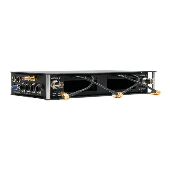
- Page 5 LEFT SIDE PANEL SHOWING: (left to right) Two 4 Pin TB4M (mini XLR) Power Connections DB-15HD Audio Output Snake Connector 4x TA3M Audio Output Connections 2 x SMA RF Outputs (loop throughs) RIGHT SIDE PANEL SHOWING: (Left to right) 5 x DC Power Distribution Outputs Dual USB Power Outputs (4 Amps available current)
- Page 6 Frequency Range Information RF DISTRIBUTION: Your new PSC RF Multi RD 4 Pack contains RF distribution designed to provide proper, clean RF distribution to your Slot Receivers. Each half of the diversity RF distribution contains a built in DC bias circuit designed to be able to power external remote powered antennas and/or remote RF amplifiers, an RF limiter to help guard against RF overload, RF bandpass filters (various ranges available), a very low noise RF Amplifier, and a RF splitter.
- Page 7 the unit is powered up. When all four LEDs are lighted, it indicates a fully charged battery. As the battery capacity drops, so will the lighted LEDs. Each LED indicates approximately 25% of the battery capacity remains: RED, YELLOW, GREEN and BLUE LEDs LIGHTED = FULL BATTERY CAPACITY RED, YELLOW and GREEN LEDs LIGHTED, = 75% BATTERY CAPACITY RED AND YELLOW LEDs LIGHTED = 50% BATTERY CAPACITY RED LED ONLY LIGHTED = 25% OR LESS BATTERY CAPACITY...
- Page 8 12.8V Sealed Lead Acid (SLA) or Lithium Iron Phosphate (LiFEPO4) STEP BY STEP USE GUIDE: 1. Install your slot style receivers into the openings on the front of the PSC RF Multi SR Four Pack noting the correct direction of the DB-25 connectors.
- Page 9 “Antenna” power switch. For all other uses, leave this switch turned off. 5. Connect the PSC RF Multi SR Four Pack cable mounted SMA connectors to your slot receivers using a “Criss cross” or X pattern. In some situations, it may make more sense to keep the RF cables aligned with the receivers rather than crossed.
-
Page 10: Specifications
SPECIFICATIONS: Size: 9.25” x 5.75” x 1.6” (23.5cm x 14cm x 4cm) Weight: 1.6 Lbs. (0.725 kg) Power: External DC, 12 to 18Vdc @ 170mA Input Impedance: 50 Ohms Input Connector: Input Impedance: 50 Ohms Output Connector: Maximum Input Signal: +13dB Noise Figure: 0.8dB... -
Page 11: Connector Pinouts
CONNECTOR PINOUTS: External DC Power: Pins 1 & 2 = Ground Pins 3 & 4 = + 12Vdc Mini XLR: Pin 1 = Ground Pin 2 = Audio + (Hi) Pin 3 = Audio - (Low) DB-15 Multipin RX1, CH1, Pin 4 = Ground Pin 14 = Audio + Pin 9 = Audio –... -
Page 12: Declaration Of Conformity
DECLARATION OF CONFORMITY STANDARD: EN 60065.2012 Power, Safety EN 55032.2012 Part 1, Emissions EN55032.2012 Part 2, Immunity MODEL: RF Multi SR Four Pack RESPONSIBLE PARTY: Professional Sound Corp. 28085 Smyth Drive Valencia, CA 91355 USA CONTACT PERSON: Ronald Meyer (661) 295-9395 TYPE OF PRODUCT: Antenna Distribution MANUFACTURER:...
Need help?
Do you have a question about the RF MULTI SR 4 PACK and is the answer not in the manual?
Questions and answers