Table of Contents
Advertisement
Quick Links
Advertisement
Table of Contents

Summary of Contents for adept technology HM140/1
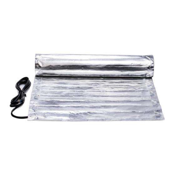
- Page 1 Foil Heating Mat System Installation Manual Floor heating System...
-
Page 2: Table Of Contents
Contents Important Safeguards and Warnings ·············································· 1 1 General Information ··············································································· 1 1.1 Use of the Manual················································································· 1 1.2 Safety Guidelines················································································· 1 1.3 Remember to measure resistance·························································· 2 1.4 Lifetime Warranty················································································· 2 2 Foil Heating Mat System ········································································ 2 2.1 Foil Heating Mat Specifications······························································ 2 2.2 Foil Heating Mat typical installations and applications······························... -
Page 3: Important Safeguards And Warnings
Important Safeguards and Warnings WARNING: Shock and fire hazard If the Foil Heating Mat System is damaged or not installed properly, fire or shock could occur resulting in serious personal injuries or damage to property. You must carefully follow the warnings and instructions contained in this manual. -
Page 4: Remember To Measure Resistance
1.3 Remember to measure resistance The resistance should be measured between the two conductors, blue and brown. Compare this resistance reading to the resistance specified in the Product Selection Table. The value should be within -5% to +10%. If you get a different reading, contact Adept at 01394 593110. Also, measure the resistance between the blue, brown and yellow green ground wire. -
Page 5: Floor Heating Design And Product Selection
wood floor Insulation board Subfloor Foil Heating Mat · Remember to measure the resistance three times. · Only for indoor installation. Do not install Foil Heating Mat in walls or ceilings. · The minimum installation temperature is 5°C(40°F). · The heating cable cannot be cut to length, crossed over itself, or installed too close. ·... -
Page 6: Confirm Your Product Selection
Figure 3: Heated area example Figure 4: Typical cold lead and floor temperature sensor 3.2 Confirm Your Product Selection Confirm that your Foil Heating Mat is no larger than the heated area. Following the example from Figure 3, if the heated area is 6.45 m , select the 6.0 m Foil Heating Mat system. -
Page 7: Installation
Table: Foil Heating Mat Product Selection 230V Heated Area Mat Dimensions Watts Amps ohms (140W/m Catalog Number sq. ft. in.*ft. 0.61 HM140/1 10.8 0.5*2 20*6.6 377.9 0.91 HM140/1.5 16.1 0.5*3 20*9.9 251.9 1.22 HM140/2 21.5 0.5*4 20*13.1 188.9 1.52 HM140/2.5 26.9... - Page 8 Calculate the internal dimensions (skirting board to skirting board) of your room and deduct 2cm from these. Using these amended dimensions sketch out a diagram of your room and calculate the total area that you have. Indicate all dimensions required to determine the available floor area and the position of the Thermostat.
- Page 9 conduit has to go from the thermostat and minimum of 25cm away from the wall towards the middle of the floor. The sensor cable should run back up to the thermostat position, the 2 core cable should be connected to the thermostat in the correct terminals. Important The sensor conduit must be centered in the cable loop (between two heating wires).
- Page 10 Begin unrolling the Foil Heating Mat evenly across the floor outside the areas that you marked previously. When you reach the next wall, cut the mesh, turn the mat, and begin rolling in the desired direction. Ensure that the Foil Heating Mat is in full contact with the insulation board at all times. Avoid walking on the heating mat.
- Page 11 Step 9: MEASURE THE RESISTANCE (THE SECOND TIME) Please refer to Step 5. Step 10: INSTALL WOOD FLOOR COVERING ENSURE THAT THE SENSOR CONDUIT HAS BEEN PROPERLY INSTALLED BEFORE PROCEEDING (see Step 3). Before fitting the floor covering switch on the heating mat to check that it is working - warmth should be noticeable on the surface of the heating mat within minutes.
-
Page 12: Commissioning
Step 11: CONNECT POWER SUPPLY AND THERMOSTAT The connection of the power supply and the Thermostat must be done by a qualified electrician. The electrician should connect the floor sensor to the thermostat, take the final resistance reading and record it on the warranty card, see Step 11. Note: need to mark the appropriate circuit breaker reference label indicating which branch circuit supplies the circuits to those electric space heating cables. -
Page 13: Sensor Resistance Test
5.3 Sensor Resistance Test This test measures the resistance of the floor sensor and is used to verify the sensor integrity. 1. Set your multimeter to the 200K ohm range. 2. Connect the multimeter leads to the red and green lead wires. -
Page 14: Troubleshooting
6 Troubleshooting Symptom Probable Causes Corrective Action No voltage. Check circuit breaker. Circuit breaker tripped. Ensure that there are not too many mats or other appliances connected on the same circuit. The Foil Heating Mat may require a dedicated circuit. See the Product Selection Table of this manual. -
Page 15: Extended Warranty
EXTENDED WARRANTY For a period of lifetime from the date of purchase Adept warrants that the Heating Mat heating cable is free from defects in material, design and workmanship. The extended warranty is only valid if the warranty certificate has been properly completed and mailed, and the installation is in accordance with the installation instructions.
Need help?
Do you have a question about the HM140/1 and is the answer not in the manual?
Questions and answers