
Subscribe to Our Youtube Channel
Related Manuals for Kentec Electronics DNX-R-2F-K

Summary of Contents for Kentec Electronics DNX-R-2F-K
- Page 1 Intelligent Network Solutions DNX-R-2F/FC-K Hybrid/RS485 and Full Optic Fibre Intelligent Network Analyser User Manual *Man-1492* Man-1492 DNX-R-2F/FC-K Rev.02...
- Page 2 Legal information The contents of this document are provided “as is”, except as required by applicable law, no warranties of any kind, either express or implied, including, but not limited to, the implied warranties of merchantability and fitness for a particular purpose, are made in relation to the accuracy and reliability or contents of this document.
-
Page 3: Prior To Installation
Safety Prior to installation: Read this manual completely and gather all information on the unit. Ensure that your application does not exceed the safe operating specifications for this unit. This unit should only be installed by qualified personnel. This unit should be built into an apparatus cabinet, or similar, where access is restricted to service personnel only. -
Page 4: Agency Approvals And Standards Compliance
Agency approvals and standards compliance Type Approval / Compliance EN 61000-6-2, Immunity Standard (Industrial Environments) EN 61000-6-4, Emission Standard (Industrial Environments) EN 60950, IT Equipment Safety Table 1 Ratings Power 18 to 36V (24V DC nominal); 170mA (at 24V) Temperature (Operating) -10 to 70°C Temperature (Storage) -40 to 70°C... -
Page 5: Safety Control Drawing
Safety Control Drawing Position Description Input / Output values RX – LC connector interface for fibre - PORT B Data rate: 100 Mb/s –125 MBd. Fibre drive distance: M: Multi-mode - up to 2km TX – LC connector interface for fibre - PORT B S: Single-mode –... -
Page 6: Functional Description
Functional description The DNX R-2F/FC are network nodes that support intelligent infrastructure monitoring of the hybrid and Optic Fibre network bus with RS-485 / ARCNET CIE interface ports A1 and A2. Figure 2: Design Structure Diagram The DNX R-2F/FC can function in one of two modes: Mode 1 as a PASSIVE dual port Optic Fibre / RS-485 medium converter. - Page 7 The additional features offered with the DNX R-2F/FC-UG license are accessed by using the IVIEW application. The license indication LED I/O 3 on the keypad is used to indicate a licensed/unlicensed state, as in Figure 20. The DNX R-2F/FC can operate in a mode with two optic fibre interfaces (2F) located on ports B and C and also in a mode with a single optic fibre interface and an RS-485 interface (FC or CF).
- Page 8 When using as a 2F module, the two Optic Fibre ports (B & C) are connected as per Figure 18a. Depending on the driver module selected, the Optic Fibre, transceiver modules can support transmission distances up to 80 km. The CIE connection to port A1 and/or A2 is via an RS-485 or ARCNET interface.
- Page 9 Figure 4c: ACTIVE or PASSIVE Mode – DNX R-2F/FC Class A Redundant Hybrid Network Figure 4d: ACTIVE or PASSIVE Mode – DNX R-2F/FC Class B Radial Hybrid Network *Note – The Class A or B mode of operation is applicable to both ACTIVE and PASSIVE Mode.
- Page 10 Figure 4e: DNX R-2F/FC Port A1 and A2 Connections The module supports 2-wire half duplex communication from CIE nodes (RS-485 / ARCNET). With the DNX R-2F/FC-UG upgrade, the module dynamically manages and protects the data bus through monitoring the data it routes. The modules are transparent to the CIE protocols, only routing and analysing the data structure but not the content.
-
Page 11: Interface Specifications
Interface specifications Power Rated voltage 18 to 36 VDC Operating voltage 17 to 42 VDC Rated current 170 mA @ 24 VDC Rated frequency Polarity Reverse polarity protection Connection Detachable screw terminal Connection size 0.2 – 2.5 mm (AWG 24-12) Table 5 RS485 Port A1, A2 &... -
Page 12: Led Indicators
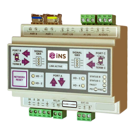
Locations of Interface ports, LEDs and DIP-switches LED Indicators Colour Status Description Signal amplitude (on RS-485) and quality LED 1 indicates that the Q &S LED C1/ Amber signal quality is greater than 20% Q &S LED B1 Signal amplitude and quality is POOR. (Q&S Debug disabled) The signal quality is less than 20%... - Page 13 Amber There is a FAULT present on the link connected to port C. There is NO fault on port C, but INSUFFICIENT DATA activity. There is a signal QUALITY FAULT present on the link connected Amber to port C. FLASH Green Port C is in a state of establishing the link FAULT identified...
- Page 14 Figure 5: Node Display Note – if ALL of the IO PORT LEDs are OFF, then the DNX R-2F/FC is in PASSIVE mode. Features included in DNX R-2F/FC (module) and DNX R-2F/FC-UG (upgrade) DNX R-2F/FC + DNX R-2F/FC-UG Feature ✓ ✓...
-
Page 15: Dip Switch Settings
DIP-switch settings Before accessing the internal DIP-switch and jumper settings: (sets 1, 2, 3, 4 & 5) Prevent damage to internal electronics from electrostatic discharges (ESD) by discharging your body to a grounding point (e.g. use of a wrist strap). For internal DIP SWITCH setting information, refer to the DNX R-2F/FC Advanced User Manual. - Page 16 Description (*DNA R-2F/FC Mode Only) Switch Set 6 Master selection (Only used in Active Mode) Slave selection (Only used in Active Mode) Commissioning Mode Enabled (Only used in Active Mode) Commissioning Mode Disabled (Only used in Active Mode) Class B - (Stops the Fault LED for indicating a fault with an open point in the bus) Class A Active Mode selection Passive Mode selection...
-
Page 17: Rotary Selector
Rotary selector switch settings for communication configuration The rotary selector switch, located on the DNX R-2F/FC as shown in Figure 7, has the setting associations shown in Table 11. Rotary selector switch Figure 7: Rotary selector Rot Switch Setting Position Function Panel Port B - Fibre... - Page 18 Not Used Not Used Not Used Not Used Not Used Not Used Not Used Not Used Not Used Table 11 Man-1492 DNX-R-2F/FC-K...
-
Page 19: Usb Connection
USB connection The USB micro (B) connector is located on the DNX R-2F/FC as indicated in Figure 8. Figure 8: USB micro (B) connector The USB is supplied with a driver that will need to be installed prior to using the USB connection. - Page 20 Unit specific description The DNX R-2F/FC module is designed to enhance the performance of the network by monitoring and optimizing the performance of the physical transmission layer. Each of the inter-node links (links between the DNX R-2F/FC nodes) are managed independently from each other.
- Page 21 Signal propagation delay and jitter Many CIE (e.g. Fire panel) only offer tight timing requirements for supporting a class A redundant ring application. With the introduction of third-party equipment into an OEM redundant transmission path, additional signal delays and jitter are often introduced with the original CIEs no longer able to function as required.
-
Page 22: Configuration And Installation
Configuration and Installation The DNX R-2F/FC modules can be used in both the “Passive” and “Active” modes of operation. The installation of the iNS should be executed in order of presentation. Configuration steps: Configure the local communication settings for each DNX R-2F/FC. The communication settings are configured for the respective fire alarm panel by setting the Rotary switch 1 in Table 11. - Page 23 Link validation procedure in ACTIVE Mode Once ACTIVE Mode has been selected, the DNX R-2F/FC modules will automatically manage the communication on either side of the fibre optic link when the modules have been powered up. The Link establishing procedure will take approximately 2 to 3 seconds to complete with the Link established LED in an ON state once the process has been completed.
- Page 24 Commissioning Mode (ACTIVE Mode only) Enable or disable the commissioning mode on the device by setting or re- setting DIP SWITCH 2 of set 6 as per selection in Table 10. Commissioning ON (Slaves) Set 6 Note: It is best practice to implement these settings in each device prior to installation.
- Page 25 5.2) DNX R-2F/FC Slaves ONLY The slave modules MUST always have the commissioning switch in the ON position during all modes of operation. With the DNX R-2F/FC in SLAVE mode (as per DIP SWITCH 1 of set 6), the commissioning mode switch is used to force the DNX R-2F/FC module to use the local communication settings on the device as per DIP switch settings instead of the global settings the master DNX R-2F/FC broadcasts during the commissioning cycle.
- Page 26 Retrieval of information from the Node The modules can be set to operate in Class A (closed ring) or Class B (radial link) by setting or resetting Switch 3 of Set 6 as indicated in the table below Note. This external switch selection of Class A or B is ONLY available from Micro Firmware version 9.8X onwards.
-
Page 27: Field Applications
Field applications Class A – Redundant ring configuration The DNX R-2F/FC module was designed to support full optic fibre class A redundancy as required for EN54-13 and BS5839-1. This topology is illustrated in Figure 11. Figure 11: Class A – Hybrid Network Class B –... - Page 28 BiDi SFP Transceivers (Bi-directional transceivers) The DNX R-2F/FC can also be used to convert a dual fibre radial link to a redundant dual path as per Figure 13 by using the BiDi SFP transceivers. The BiDi transceivers use two frequencies for Tx and Rx on each fibre to carry the Tx and Rx signals on a single fibre.
- Page 29 RS-485 cable screen connection with the DNX R-2F/FC used in hybrid medium mode When the DNX R-2F/FC is used in hybrid medium mode, the screen on the metallic conductor (cable) needs to be earthed on one of the two sides to provide a path to ground any coupled signal interference.
- Page 30 Mixed Optic Fibre cable types (e.g. Single Mode and Multi-mode) The DNX R-2F/FC supports a network that has mixed cable types by selecting the correct SFP transceiver for the cable to which it is connected. Transceiver types supported: Multi-mode (MM) Single Mode (SM) Bi-directional (BiDi) Figure 15: Connections of Mixed Optic Fibre Types...
- Page 31 Multi-Protocol configuration This feature is ONLY available once the feature is unlocked with a license procured from a distributor. With the feature available, refer to SWITCH 1 of set 4 to enable or disable the multi-protocol function. (Internal switch as per an Advanced User Guide) The DNX R-2F/FC-L network supports a multi-protocol bus on optic fibre.
- Page 32 Power supply monitoring The DNX R-2F/FC module can monitor the dual power supplies for either “out of limits” operation or total failure. The events are automatically recorded for recovery on request using additional iNS tools. A typical example of a configuration for monitoring the auxiliary and backup battery power supplies is illustrated in Figure 17a.
-
Page 33: Earth Terminal
About the interfaces Power terminal The power terminal has two independent inputs, +Voltage A and +Voltage B. These have been included to support redundancy should either of the two fail. The DNX R- 2F/FC power supply is galvanically isolated from all other internal electronics. RS-485 interface Two connectors with three-position detachable screw terminals support the connections for the 4 port 2 wire RS-485 system. -
Page 34: Referring Documents
Mounting This unit should be mounted on 35 mm DIN-rail, which is horizontally mounted inside an apparatus cabinet, or similar. The mounting is of the “snap on” type. Referring documents Information relating to specific application of this device can be found in the following application notes. -
Page 35: Wiring Connections
Wiring connections Figure 18a and 18b illustrates the wiring connections for the DNX R-2F/FC modules. Note: The port connections must have Port B connected to Port C as reflected in the diagram. Figure 18a: Passive Mode Settings and Dual Port CIE Connections Man-1492 DNX-R-2F/FC-K... - Page 36 Figure 18b: Passive Mode Settings and Dual Port CIE with Hybrid Connections Man-1492 DNX-R-2F/FC-K...
-
Page 37: Sfp Transceivers
SFP Transceivers The SFP transceivers used with the DNX R-2F/FC product are presented in Figure 19. Figure 19a: INS010 – Multimode transceiver Figure 19b: INS011 – Single mode transceiver Figure 19c: INS012 – Single mode Bi-directional transceiver (To pair with the INS013) Figure 19d: INS013 –... - Page 38 Figure 20: iNS LED Indication Man-1492 DNX-R-2F/FC-K...
- Page 39 Figure 20a: iNS LED Indication Man-1492 DNX-R-2F/FC-K...
- Page 40 Notes Man-1492 DNX-R-2F/FC-K...
- Page 41 Man-1492 DNX-R-2F/FC-K...
- Page 42 Man-1492 DNX-R-2F/FC-K...
Need help?
Do you have a question about the DNX-R-2F-K and is the answer not in the manual?
Questions and answers