
Related Manuals for Kentec Electronics DNX-A-2R-K

Summary of Contents for Kentec Electronics DNX-A-2R-K
- Page 1 Intelligent Network Solutions DNX-A-2R-K RS485 Intelligent Network Analyser User Manual *Man-1491* Man-1491 Rev.02...
- Page 2 Under no circumstances shall Kentec be responsible for any loss of data or income or any special, incidental, and consequential or indirect damages howsoever caused. More information about Kentec can be found at the following Internet address: http://www.kentec.co.uk Man-1491 DNX-A-2R-K User Manual...
-
Page 3: Prior To Installation
If the unit is not working properly, contact the place of purchase, nearest Kentec distributor office, or Kentec Tech support. Maintenance No maintenance is required, as long as the unit is used as intended within the specified conditions. Man-1491 DNX-A-2R-K User Manual... -
Page 4: Agency Approvals And Standards Compliance
EN 61000-6-4, Emission Standard (Industrial Environments) EN 60950, IT Equipment Safety Table 1 Ratings Power 18 to 36V (24V DC nominal); 250mA (at 24V) Temperature (Operating) -10 to 70°C Temperature (Storage) -40 to 70°C Ingress protection (IP) IP20 Table 2 Man-1491 DNX-A-2R-K User Manual... -
Page 5: Safety Control Drawing
In / Out / - line RS-485 – IO Interface Umax = ± 5Vpk Imax = ± 60 mA In / Out / + line RS-485 – IO Interface Data rate: Screen/Shield RS-485 – IO Interface 4.8 to 115.2 kbit/s Table 4 Man-1491 DNX-A-2R-K User Manual... -
Page 6: Functional Description
(ACTIVE mode is required for use as a network analysis tool) The mode can be selected through Set 5 switch 1 in Figure 5c and Table 11. Note* The DNX-A-2R-K will operate in a basic mode unless upgraded to unlock the additional features offered by the firmware upgrade (DNX-R-2R-K-UG). - Page 7 When using the shield on all of the cables between ports B and C, it is recommended that the shield connection to port C of the DNX-A-2R-K be left disconnected. This is done so that each link between nodes is only grounded at one end to avoid ground loops in the network.
- Page 8 Figure 4: DNX-A-2R-K, DNX-R-2F/FC-K-2F/FC Port A1 and A2 Connections Man-1491 DNX-A-2R-K User Manual...
-
Page 9: Interface Specifications
Full speed device mode as per USB 2.0 specification Data format As per USB specification Connector type USB micro B (device) - cable type micro B required Implementation mode Slave Protection Transient voltage protection Table 8 Man-1491 DNX-A-2R-K User Manual... -
Page 10: Led Indicators
Port A TX No valid data has been transmitted out of port A Green A good data packet has been received on port A Port A RX No valid data has been received on port A Man-1491 DNX-A-2R-K User Manual... - Page 11 Port A has been internally disconnected – corrupt data received Amber No corrupt data on port A FLASH Unused IO PORT LED 4 Configured as Master Node Green Configured as Slave Node FLASH Unused Table 9 Man-1491 DNX-A-2R-K User Manual...
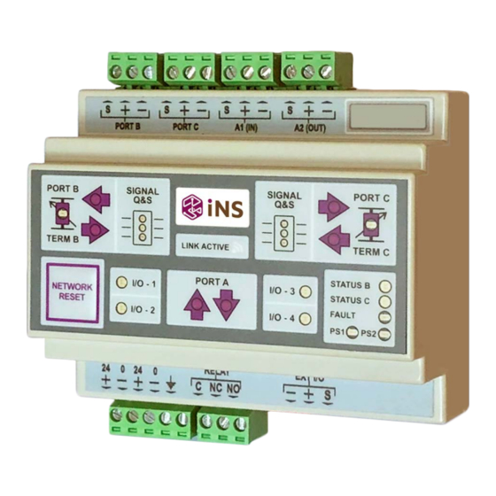
- Page 12 Figure 4a: Node fascia Note – if ALL of the IO PORT LEDs are OFF, then the DNX-A-2R-K is in PASSIVE mode. Features included in DNX-A-2R-K (module) and DNX-R-2R-K-UG (upgrade) DNX-A-2R-K + upgrade Feature ✓ ✓ Passive mode of operation ✓...
-
Page 13: Dip Switch Settings
(e.g. use of a wrist strap). For internal DIP SWITCH setting information, refer to the DNX-A-2R-K Advanced User Manual. The configuration setting for use with Kentec fire alarm panels has been simplified so that you only need to set external switches. - Page 14 Set 1 - Switch 1,2 & 4 Master selection Slave selection Commissioning Mode Enabled Commissioning Mode Disabled DNX-A-2R-K node in class A configuration (redundant ring) DNX-A-2R-K node in class B configuration (radial) Table 10 Description Set 5 - Switch 1...
- Page 15 Switch set 5 switch 2 is used to select the Fire panel with which the product will be used. The switch located on the DNX-A-2R-K as shown in Figure 6, has the respective setting association as presented in Table 12.
-
Page 16: Usb Connection
USB connection The USB micro (B) connector is located on the DNX-A-2R-K as indicated in Figure 7. Figure 7: USB micro (B) connector The USB is supplied with a driver that will need to be installed prior to using the USB connection. - Page 17 Although each link in the transmission path will be optimised for performance, the maximum data rate will be limited to the poorest performing link in the network. Figure 8 illustrates the independent links in a typical class A DNX-A-2R-K application.
- Page 18 B and C on either side of an RS-485 link between neighbouring DNX- A-2R-K modules. The optimisation procedure will not be supported without enabling the auto-termination of the DNX-A-2R-K port node located on the respective side of the RS-485 link.
- Page 19 With the introduction of third-party equipment into an OEM redundant transmission path, additional signal delays and jitter are often introduced with the original CIEs no longer able to function as required. The DNX-A-2R-K modules are designed to support extended signal delays and jitter. When used with the installed CIEs, these modules can provide a functional class A redundant solution that is tolerant of most delays and jitter.
-
Page 20: Configuration And Installation
When using the DNX-A-2R-K modules, a master is required for commissioning the network and managing the fault recovery procedure. It is important that there is only a single (ONE) DNX-A-2R-K master per class A ring or class B radial. Adjust the Master/Slave selection on the device by setting or re-setting DIP SWITCH 1 of Set 1 as per selection in Table10. - Page 21 Figure 10. Figure 10 The DNX-A-2R-K modules can be used in either a class A configuration as presented in Figure 11, or a class B configuration as presented in Figure 12. Port B should always be connected to port C of the neighbouring module as per Figure 11 and 12.
- Page 22 With the DNX-A-2R-K in MASTER mode (as per DIP SWITCH 1 of set 1), the commissioning mode switch is used to force the DNX-A-2R-K module to manage commissioning by auto-allocating addresses, broadcasting operational details and presenting a global status map.
- Page 23 Replacement of failed module in circuit In the event of an DNX-A-2R-K module failure, the module can be easily replaced with a spare module that has been configured as per steps 1 to 6. The module will be included into the network on power-up to normal communication of the network, without the need to re-commission the network DNX-A-2R-K nodes (section 5).
-
Page 24: Field Applications
Field applications Class A – Redundant ring configuration The RS-485 DNX-A-2R-K module was designed to support full class A redundancy as required for EN54-13 and BS5839-1. This topology is illustrated in Figure 11. Figure 11: Class A redundant network Class B – Non-redundant radial configuration... - Page 25 Information relating to the use of this product for the implementation of the multi- protocol functionality can be found in the DNX-A-2R-K-L Advanced Manual. The DNX-A-2R-K-L supports two protocols, each with a maximum baud rate limitation of 38400 baud. The performance of the network is however also dependent on the length of the various cable links and cable types.
- Page 26 RS-485 transceivers etc. The recommended communication medium for introducing the multi-protocol feature, is optic fibre with the DNX-R-2F/FC-K product. Man-1491 DNX-A-2R-K User Manual...
- Page 27 Power supply monitoring The DNX-A-2R-K module can monitor the dual power supplies for either “out of limits” operation or total failure. The events are automatically recorded for recovery on request using additional Kentec tools. A typical example of a configuration for monitoring the auxiliary and backup battery power supplies is illustrated in Figure 14.
-
Page 28: Earth Terminal
During a power failure the relay contacts open to indicate a fault. Note: A power failure condition with a simultaneous failure of PSU1 and PSU2, will only be identified by the relay state and not reflected on the LED indication. Man-1491 DNX-A-2R-K User Manual... - Page 29 If the unit is not working properly, contact the place of purchase, nearest Kentec distributor office or Kentec Tech support. Mounting This unit should be mounted on 35 mm DIN-rail, which is horizontally mounted inside an apparatus cabinet, or similar. The mounting is of the “snap on” type. Man-1491 DNX-A-2R-K User Manual...
-
Page 30: Wiring Connections
Wiring connections Figure 16 illustrates the wiring connections for the DNX-A-2R-K modules. Note The port connections must have Port B connected to Port C as reflected in the diagram. Figure 16 Man-1491 DNX-A-2R-K User Manual... - Page 31 Notes Man-1491 DNX-A-2R-K User Manual...
- Page 32 Notes Man-1491 DNX-A-2R-K User Manual...
- Page 33 Man-1491 DNX-A-2R-K User Manual...
- Page 34 DNX-A-2R-K LED Indication REFERENCE: (2 PAGES) Man-1491 DNX-A-2R-K User Manual...
- Page 35 Man-1491 DNX-A-2R-K User Manual...
Need help?
Do you have a question about the DNX-A-2R-K and is the answer not in the manual?
Questions and answers