Table of Contents
Advertisement
Quick Start
Thank you for purchasing the MSI®
section provides demonstration diagrams about how to install your computer. Some
of the installations also provide video demonstrations. Please link to the URL to watch
it with the web browser on your phone or tablet. You may have even link to the URL by
scanning the QR code.
Preparing Tools and Components
Intel® LGA1700 CPU
DDR5 Memory
Thermal Paste
Phillips Screwdriver
MEG Z690 UNIFY-X
LGA1700 CPU Fan
Power Supply Unit
SATA Hard Disk Drive
motherboard. This Quick Start
Graphics Card
SATA DVD Drive
A Package of Screws
Chassis
1
Quick Start
Advertisement
Table of Contents

Related Manuals for MSI MEG Z690 UNIFY-X


Summary of Contents for MSI MEG Z690 UNIFY-X
-
Page 1: Quick Start
Quick Start Thank you for purchasing the MSI® MEG Z690 UNIFY-X motherboard. This Quick Start section provides demonstration diagrams about how to install your computer. Some of the installations also provide video demonstrations. Please link to the URL to watch it with the web browser on your phone or tablet. -
Page 2: Safety Information
Safety Information ∙ The components included in this package are prone to damage from electrostatic discharge (ESD). Please adhere to the following instructions to ensure successful computer assembly. ∙ Ensure that all components are securely connected. Loose connections may cause the computer to not recognize a component or fail to start. -
Page 3: Case Stand-Off Notification
Case stand-off notification To prevent damage to the motherboard, any unnecessary mounting stand-off between the motherboard circuits and the computer case is prohibited. The Case standoff keep out zone signs will be marked on the backside of motherboard (as shown below) to serve as a warning to user. -
Page 4: Installing A Processor
Installing a Processor ⚽ https://youtu.be/KMf9oIDsGes Quick Start... -
Page 5: Installing Ddr5 Memory
Installing DDR5 memory ⚽ https://youtu.be/XiNmkDNZcZk DIMMB1 DIMMA1 DIMMB1 Quick Start... -
Page 6: Connecting The Front Panel Header
Connecting the Front Panel Header ⚽ http://youtu.be/DPELIdVNZUI Power LED Power Switch JFP1 Reserved HDD LED Reset Switch HDD LED + Power LED + HDD LED - Power LED - Reset Switch Power Switch JFP1 Reset Switch Power Switch Reserved No Pin HDD LED - HDD LED HDD LED +... -
Page 7: Installing The Motherboard
Installing the Motherboard ⚽ https://youtu.be/wWI6Qt51Wnc Torque: 3 kgf·cm* *3 kgf·cm = 0.3 N·m = 2.6 lbf·in Quick Start... -
Page 8: Connecting The Power Connectors
Connecting the Power Connectors ⚽ http://youtu.be/gkDYyR_83I4 ATX_PWR1 CPU_PWR2 CPU_PWR1 Quick Start... -
Page 9: Installing Sata Drives
Installing SATA Drives ⚽ http://youtu.be/RZsMpqxythc Quick Start... -
Page 10: Installing A Graphics Card
Installing a Graphics Card ⚽ http://youtu.be/mG0GZpr9w_A Quick Start... -
Page 11: Connecting Peripheral Devices
Connecting Peripheral Devices Quick Start... -
Page 12: Power On
Power On Quick Start... -
Page 13: Table Of Contents
Contents Quick Start ......................1 Preparing Tools and Components................1 Safety Information ....................2 Case stand-off notification ..................3 Avoid collision notification ..................3 Installing a Processor .................... 4 Installing DDR5 memory ..................5 Connecting the Front Panel Header ..............6 Installing the Motherboard .................. - Page 14 Boot Phases ......................56 Debug Code LED Table ..................57 ACPI States Codes ....................61 CPU Temperature ....................61 Installing OS, Drivers & MSI Center ..............62 Installing Windows® 10 ..................62 Installing Drivers ....................62 MSI Center ......................62 UEFI BIOS ......................
-
Page 15: Specifications
Specifications ∙ Supports 12th Gen Intel® Core™, Pentium® Gold and Celeron® Processors* ∙ Processor socket LGA1700 * Please go to www.msi.com to get the newest support status as new processors are released. Chipset Intel® Z690 Chipset ∙ 2x DDR5 memory slots, support up to 64GB* ∙... - Page 16 Continued from previous page ∙ Supports NVIDIA® SLI Technology Multi-GPU ∙ Supports AMD® CrossFire™ Technology ∙ 6x SATA 6Gb/s ports ▪ SATA5~8 (From Z690 Chipset) ▪ SATAA~B1 (From ASMedia ASM1061) ∙ 5x M.2 slots (Key M) ▪ M2_1 slot (From CPU) ▫...
- Page 17 Continued from previous page Intel® Wi-Fi 6E ∙ The Wireless module is pre-installed in the M.2 (Key-E) slot ∙ Supports MU-MIMO TX/RX, 2.4GHz/ 5GHz/ 6GHz* (160MHz) up to 2.4Gbps Wireless LAN & Bluetooth® ∙ Supports 802.11 a/ b/ g/ n/ ac/ ax ∙...
- Page 18 Continued from previous page ∙ 1x Clear CMOS jumper ∙ 1x Slow mode jumper Jumpers ∙ 2x Low temperature booting jumpers ∙ 1x Safe boot jumper ∙ 1x OC Retry jumper ∙ 1x 2-Digit Debug Code LED ∙ 4x EZ Debug LED LED Features ∙...
- Page 19 ∙ Drivers ∙ MSI Center ∙ Intel Extreme Tuning Utility ∙ Nahimic Software ∙ MSI APP Player (Bluestack) ∙ Open Broadcaster Software (OBS) ∙ CPU-Z MSI GAMING ∙ Google Chrome™, Google Toolbar, Google Drive ∙ Norton™ Internet Security Solution ∙ Duet Display ∙...
- Page 20 Continued from previous page ∙ Audio ▪ Audio Boost 5 ▪ Nahimic 3 ▪ Sound Tune ∙ Network ▪ 2.5G LAN ▪ LAN Manager ▪ Intel WiFi ∙ Cooling ▪ All Aluminum Design ▪ Heat-pipe Design ▪ Extended Heatsink Design Special Features ▪...
- Page 21 ▪ 2oz Copper thickened PCB ∙ Protection ▪ PCI-E Steel Armor ▪ Pre-installed I/O Shield ∙ Experience ▪ Smart Button ▪ MSI Center ▪ Frozr AI Cooling ▪ Click BIOS 5 ▪ System Saver ▪ Flash BIOS Button ▪ EZ M.2 Clip ▪...
-
Page 22: Package Contents
Package contents Please check the contents of your motherboard package. It should contain: Motherboard MEG Z690 UNIFY-X User manual Documentation Quick installation guide Application USB drive with drivers & utilities SATA 6Gb/s cables LED JRGB Y cable LED JCORSAIR cable... -
Page 23: Block Diagram
Block Diagram PCI_E1 PCIe x16 PCI_E2 DDR5 PCIe x8 DIMM A1 DIMM B1 M2_1 DMI x8 USB3.2 Gen2x2 20Gbps PCI_E3 PCIe 3.0 x4 USB 3.2 Gen 2 10Gbps M2_2, M2_3, M2_4, M2_5 USB 3.2 Gen 2 GL3590- 10Gbps OTY10 SATA5/6/7/8 USB 3.2 Gen 1 5Gbps 1074 SATAA/B... -
Page 24: Rear I/O Panel
Rear I/O Panel Audio Ports 2.5Gbps LAN Clear CMOS PS/2 button USB 2.0 Optical USB 3.2 Gen 2 Type A S/PDIF-Out 10Gbps Type A Flash BIOS Flash BIOS USB 3.2 Gen 2x2 Wi-Fi Antenna Button port (20Gbps) Type-C connectors ∙ Flash BIOS Port/ Button - Please refer to page 66 for Updating BIOS with Flash BIOS Button. -
Page 25: Realtek Audio Console
Realtek Audio Console After Realtek Audio Console is installed. You can use it to change sound settings to get better sound experience. Application Enhancement Device Selection Main Volume Connector Settings Jack Status ∙ Device Selection - allows you to select a audio output source to change the related options. - Page 26 Audio jacks to headphone and microphone diagram Audio jacks to stereo speakers diagram AUDIO INPUT Audio jacks to 7.1-channel speakers diagram AUDIO INPUT Rear Front Side Center/ Subwoofer Rear I/O Panel...
-
Page 27: Installing Antennas
Installing Antennas 1. Combine the antenna with the base. 2. Screw two antenna cables tight to the WiFi antenna connectors as shown. 3. Place the antenna as high as possible. Rear I/O Panel... -
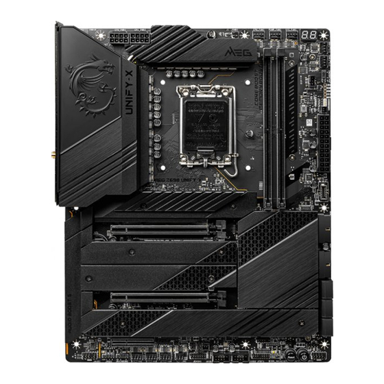
Page 28: Overview Of Components
Overview of Components Processor Socket CPU_FAN1 CPU_PWR2 DIMMB1 PUMP_FAN1 CPU_PWR1 DIMMA1 SYS_FAN1 SYS_FAN6 SYS_FAN5 JRAINBOW2 JCORSAIR1 T_SEN1 ATX_PWR1 JUSB5 M2_1 JUSB3 PCI_E1 M2_5 M2_2 JUSB4 M2_3 SATA▼5▲6 PCI_E2 SATA▼7▲8 JLN1,JLN2,JCI1 M2_4 SATA▼A▲B1 JBAT1 PCI_E3 JFP2 JFP1 SYS_ POWER1 FAN3 RESET1 SYS_FAN4 BIOS_SW1 JAUD1... - Page 29 Component Contents Port Name Port Type Page BIOS_SW1 Multi-BIOS Switch CPU_FAN1, PUMP_FAN1, Fan Connectors SYS_FAN1~6 CPU_PWR1~2, ATX_PWR1 Power Connectors CPU Socket LGA1700 CPU Socket DIMM Slots Memory slots JAUD1 Front Audio Connector JBAT1 Clear CMOS (Reset BIOS) Jumper JCI1 Chassis Intrusion Connector JCORSAIR1 CORSAIR Connector JDASH1...
-
Page 30: Cpu Socket
∙ the CPU. ∙ Please retain the CPU protective cap after installing the processor. MSI will deal with Return Merchandise Authorization (RMA) requests if only the motherboard comes with the protective cap on the CPU socket. When installing a CPU, always remember to install a CPU heatsink. A CPU heatsink ∙... -
Page 31: Dimm Slots
It is recommended to use a more efficient memory cooling system for full DIMMs ∙ installation or overclocking. The stability and compatibility of installed memory module depend on installed CPU ∙ and devices when overclocking. ∙ Please refer to www.msi.com for more information on compatible memory. Overview of Components... -
Page 32: Pci_E1~3: Pcie Expansion Slots
⚠ Important ∙ If you install a large and heavy graphics card, you need to use a tool such as MSI Graphics Card Bolster to support its weight to prevent deformation of the slot. ∙ For a single PCIe x16 expansion card installation with optimum performance, using the PCI_E1 slot is recommended. -
Page 33: Jfp1, Jfp2: Front Panel Connectors
3. Connect all PCIe power connectors of the graphics cards. 4. Reconnect the power cord, power up the computer and install the drivers and software included in your graphics card package. 5. Right-click the Windows desktop and select NVIDIA Control Panel from the menu, click on Configure SLI, Surround, PhysX in the left task pane and select Maximize 3D performance in the SLI configuration menu, and then click Apply. -
Page 34: M2_1~5: M.2 Slots (Key M)
M2_1~5: M.2 Slots (Key M) ⚠ Important ∙ Intel® RST only supports PCIe M.2 SSD with UEFI ROM. Intel® Optane™ Memory Ready for M2_2~5 ∙ slots. M2_1 M2_2 M2_3 M2_5 M2_4 M2_1, M2_2 slots Installation 1. Loosen the screws of M.2 SHIELD FROZR heatsink. 2. - Page 35 4. If you install 2260 SSD, remove the screw from the M.2 plate and then install supplied EZ M.2 Clip kit on the M.2 plate. Skip this step, if you install 2280 SSD. 2260 SSD 5. Insert your M.2 SSD into the M.2 slot at a 30-degree angle. 6.
- Page 36 M2_3 slot Installation 1. Loosen the screws of M.2 SHIELD FROZR heatsink. 2. Remove the M.2 SHIELD FROZR and remove the protective films from the thermal pads. 3. Remove the protective films from the M.2 thermal pads on the M.2 plate. 4.
- Page 37 30º 30º 30º 30º 2280 SSD 2260 SSD 22110 SSD 7. Put the M.2 SHIELD FROZR heatsink back in place and secure it. Overview of Components...
- Page 38 M2_4, M2_5 slots installation 1. Loosen the screws of M.2 SHIELD FROZR heatsink. 2. Remove the M.2 SHIELD FROZR and remove the protective films from the thermal pads. 3. Remove the protective films from the M.2 thermal pads on the M.2 plate. Overview of Components...
- Page 39 4. If there is a screw installed on the M.2 plate, remove it first; otherwise, please skip this step. 5. Secure the supplied M.2 standoff according to your M.2 SSD length. Standoff 6. Insert your M.2 SSD into the M.2 slot at a 30-degree angle. 7.
-
Page 40: Sata5~8 & Sataa~B1: Sata 6Gb/S Connectors
8. Put the M.2 SHIELD FROZR heatsink back in place and secure it. SATA5~8 & SATAA~B1: SATA 6Gb/s Connectors These connectors are SATA 6Gb/s interface ports. Each connector can connect to one SATA device. SATA6 SATA5 SATA8 SATA7 SATAB1 SATAA ⚠... -
Page 41: Cpu_Pwr1~2, Atx_Pwr1: Power Connectors
CPU_PWR1~2, ATX_PWR1: Power Connectors These connectors allow you to connect an ATX power supply. CPU_PWR1~2 Ground +12V Ground +12V Ground +12V Ground +12V +3.3V +3.3V +3.3V -12V Ground Ground PS-ON# Ground Ground Ground ATX_PWR1 Ground Ground PWR OK 5VSB +12V +12V +3.3V Ground... -
Page 42: Jslow1: Slow Mode Booting Jumper
JSLOW1: Slow Mode Booting Jumper This jumper is used for LN2 cooling solution, that provides the extreme overclocking conditions, to boot at a stable processor frequency and to prevent the system from crashing. Normal Enabled (Default) (Please enable this jumper during BIOS POST.) JLN1~2: Low Temperature Booting Jumper This jumper is used for liquid nitrogen cooling system to boot at an extreme low... -
Page 43: Jdash1 : Tuning Controller Connector
JDASH1 : Tuning Controller connector This connector is used to connect an optional Tuning Controller module. No Pin MCU_SMB_SCL_M MCU_SMB_SDA_M VCC5 Ground PSIN#_R FP_RST#_R OC_RETRY# OC_FS BLK+ BLK- CLRCMOS_EN Connecting the JDASH1 and Tuning Controller module OC button+ OC Fail Save Debug Code LED Reset Clear CMOS... - Page 44 Tuning Controller module magnet Tuning controller module has build in some magnets on both sides that will be convenient for you to stick it to the chassis. However, we provide extra four magnets for sticking inside the back cover of module. Please follow the instructions below to stick the magnets.
-
Page 45: Joc_Fs1: Safe Boot Jumper
JOC_FS1: Safe Boot Jumper This jumper is used for Safe Boot. Once enabled, the system will boot with default settings and lower PCIe (from CPU) mode. Normal Enabled (default) Apply the BIOS default settings and lower PCIe Boot with the saved (from CPU) mode for BIOS settings. -
Page 46: Jaud1: Front Audio Connector
JAUD1: Front Audio Connector This connector allows you to connect audio jacks on the front panel. MIC L Ground MIC R Head Phone R MIC Detection SENSE_SEND No Pin Head Phone L Head Phone Detection JTBT1: Thunderbolt Add-on Card Connector This connector allows you to connect the add-on Thunderbolt I/O card. -
Page 47: Jusb5: Usb 3.2 Gen 2X2 Type-C Connector
JUSB5: USB 3.2 Gen 2x2 Type-C Connector This connector allows you to connect USB 3.2 Gen 2x2 Type-C connector on the front panel. The connector possesses a foolproof design. When you connect the cable, be sure to connect it with the corresponding orientation. USB Type-C Cable JUSB5 USB Type-C port on... -
Page 48: Jusb1~2: Usb 2.0 Connectors
∙ In order to recharge your iPad, iPhone and iPod through USB ports, please install MSI® Center utility. JTPM1: TPM Module Connector This connector is for TPM (Trusted Platform Module). Please refer to the TPM security platform manual for more details and usages. -
Page 49: Cpu_Fan1, Pump_Fan1, Sys_Fan1~6: Fan Connectors
CPU_FAN1, PUMP_FAN1, SYS_FAN1~6: Fan Connectors Fan connectors can be classified as PWM (Pulse Width Modulation) Mode or DC Mode. PWM Mode fan connectors provide constant 12V output and adjust fan speed with speed control signal. DC Mode fan connectors control fan speed by changing voltage. The auto mode fan connectors can automatically detect PWM and DC mode. -
Page 50: T_Sen1~2: Thermal Sensor Connector
T_SEN1~2: Thermal Sensor Connector This connector allows you to connect the thermistor cable and use it to monitor the temperature of the detection point. Thermistor cable (optional) Sense V-Check Points Lite These voltage checkpoints are used to measure the current system voltages. A multimeter (not included) will be required to check voltages. -
Page 51: Jci1: Chassis Intrusion Connector
JCI1: Chassis Intrusion Connector This connector allows you to connect the chassis intrusion switch cable. Normal Trigger the chassis (default) intrusion event Using chassis intrusion detector 1. Connect the JCI1 connector to the chassis intrusion switch/ sensor on the chassis. 2. -
Page 52: Jbat1: Clear Cmos (Reset Bios) Jumper
(Default) ⚠ Important Do not use the Multi-BIOS switch when system is booting up. ∙ You can also use the MSI Center or Flash BIOS Button to flash BIOS. Please refer to ∙ BIOS section for details. Overview of Components... -
Page 53: Jrgb1: Rgb Led Connector
(12V/G/R/B) with the maximum power rating of 3A (12V). Always turn off the power supply and unplug the power cord from the power outlet ∙ before installing or removing the RGB LED strip. Please use MSI’s software to control the extended LED strip. ∙ Overview of Components... -
Page 54: Jrainbow1~2: Addressable Rgb Led Connectors
(5V). In the case of 20% brightness, the connector supports up to 200 LEDs. ∙ Always turn off the power supply and unplug the power cord from the power outlet before installing or removing the RGB LED strip. Please use MSI’s software to control the extended LED strip. ∙ Overview of Components... -
Page 55: Jcorsair1: Corsair Connector
The JCORSAIR1 connector allows you to connect the CORSAIR Individually Addressable Lighting PRO RGB LED strips 5V or CORSAIR RGB fans with the CORSAIR fan hub. Once all items are connected properly, you can control the CORSAIR RGB LED strips and fans with MSI's software. Data Ground... -
Page 56: Onboard Leds
Onboard LEDs EZ Debug LED These LEDs indicate the debug status of the motherboard. CPU - indicates CPU is not detected or fail. DRAM - indicates DRAM is not detected or fail. VGA - indicates GPU is not detected or fail. BOOT - indicates the booting device is not detected or fail. -
Page 57: Debug Code Led Table
Debug Code LED Table SEC Progress Codes Power on. Reset type detection (soft/hard) AP initialization before microcode loading System Agent initialization before microcode loading PCH initialization before microcode loading Microcode loading AP initialization after microcode loading System Agent initialization after microcode loading PCH initialization after microcode loading Cache initialization SEC Error Codes... - Page 58 CPU post-memory initialization. System Management Mode (SMM) initialization Post-Memory System Agent initialization is started 38 - 3A Post-Memory System Agent initialization (System Agent module specific) Post-Memory PCH initialization is started 3C - 3E Post-Memory PCH initialization (PCH module specific) DXE IPL is started PEI Error Codes Memory initialization error.
- Page 59 PCH devices initialization 73 - 77 PCH DXE Initialization (PCH module specific) ACPI module initialization CSM initialization 7A - 7F Reserved for future AMI DXE codes Boot Device Selection (BDS) phase is started Driver connecting is started PCI Bus initialization is started PCI Bus Hot Plug Controller Initialization PCI Bus Enumeration 32 PCI Bus Request Resources...
- Page 60 Runtime Set Virtual Address MAP End Legacy Option ROM Initialization System Reset USB hot plug PCI bus hot plug Clean-up of NVRAM Configuration Reset (reset of NVRAM settings) B8 - BF Reserved for future AMI codes DXE Error Codes CPU initialization error System Agent initialization error PCH initialization error Some of the Architectural Protocols are not available...
-
Page 61: Acpi States Codes
S3 Resume Boot Script Error S3 OS Wake Error EC - EF Reserved for future AMI error codes Recovery Progress Codes Recovery condition triggered by firmware (Auto recovery) Recovery condition triggered by user (Forced recovery) Recovery process started Recovery firmware image is found Recovery firmware image is loaded F5 - F7 Reserved for future AMI progress codes... -
Page 62: Installing Os, Drivers & Msi Center
MSI Center is an application that helps you easily optimize game settings and smoothly use content creation softwares. It also allows you to control and synchronize LED light effects on PCs and other MSI products. With MSI Center, you can customize ideal modes, monitor system performance, and adjust fan speed. -
Page 63: Uefi Bios
UEFI has many new functions and advantages that traditional BIOS cannot achieve, and it will completely replace BIOS in the future. The MSI UEFI BIOS uses UEFI as the default boot mode to take full advantage of the new chipset’s capabilities. -
Page 64: Bios Setup
* When you press F10, a confirmation window appears and it provides the modification information. Select between Yes or No to confirm your choice. BIOS User Guide If you’d like to know more instructions on setting up the BIOS, please refer to http://download.msi.com/manual/mb/Intel600BIOS.pdf or scan the QR code to access. UEFI BIOS... -
Page 65: Resetting Bios
Updating BIOS Updating BIOS with M-FLASH Before updating: Please download the latest BIOS file that matches your motherboard model from MSI website. And then save the BIOS file into the USB flash drive. Updating BIOS: 1. Switch to the target BIOS ROM by Multi-BIOS switch. Please skip this step if your motherboard doesn't has this switch. - Page 66 1. Please download the latest BIOS file that matches your motherboard model from the MSI® website. 2. Rename the BIOS file to MSI.ROM, and save it to the root of the USB storage device. 3. Connect the power supply to CPU_PWR1 and ATX_PWR1. (No need to install CPU and memory.)
-
Page 67: Raid Configuration
All the information/ volumes/ pictures listed in your system might differ from the illustrations in this appendix. Intel RAID User Guide If you’d like to know more instructions on how to set up Intel RAID, please refer to http://download.msi.com/manual/mb/IntelRAID600.pdf or scan the QR code to access. RAID Configuration... -
Page 68: Intel® Optane™ Memory Configuration
Optane™ memory, please note that it requires Windows 10 64-bit operating system. Intel® Optane™ Memory User Guide If you’d like to know more instructions on how to enable or remove Intel® Optane™ Memory, please refer to http://download.msi.com/manual/mb/Optane600.pdf or scan the QR code to access. ⚠ WARNING After you enable Intel®... -
Page 69: Troubleshooting
Troubleshooting Lost BIOS password Before sending the motherboard for RMA repair, try to go over troubleshooting ∙ Clear the CMOS, but that will cause guide first to see if your got similar you to lose all customized settings in the symptoms as mentioned below. - Page 70 제조년월: 2021년 R-R-MSI-20-7D28 제조자 및 제조국가: MSI/중국 y Visit the MSI website and locate a nearby distributor for further recycling information. y Users may also reach us at gpcontdev@msi.com for information regarding proper Disposal, Take-back, Recycling, and Disassembly of MSI products.
- Page 71 MSI will comply with the product take estos residuos. back requirements at the end of life of MSI-branded NEDERLANDS products that are sold into the EU.
- Page 72 Products can be operated without del suo ciclo di vita. MSI si adeguerà a tale Direttiva maintaining a separation distance unless otherwise ritirando tutti i prodotti marchiati MSI che sono stati indicated in instructions specific to the product.
- Page 73 Copyright © 2021 All rights reserved. contact your place of purchase or local distributor. The MSI logo used is a registered trademark of Alternatively, please try the following help resources Micro-Star Int’l Co., Ltd. All other marks and names for further guidance.
Need help?
Do you have a question about the MEG Z690 UNIFY-X and is the answer not in the manual?
Questions and answers