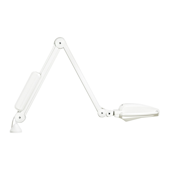
Summary of Contents for Burton NOVA LED NXT
- Page 1 NOVA LED Floor Stand, Wall, Table and Ceiling Instructions for Use & Maintenance 5000781 Rev A01 Instructions for Use...
- Page 3 NOVA LED Task & Examination Light BASE MODEL MOUNT AREA T (table) FL (floor) BLANK (United States, 120V) W (wall) C (ceiling) Example; NXFL is a floor model for the US...
-
Page 4: Table Of Contents
Preventive Maintenance Checklists ..............12 2.3. Cleaning ......................12 2.4. Replacement Parts .................... 13 Symbols and Warnings ....................13 3.1. Symbols ......................13 3.2. Cautions ......................13 3.3. Warnings ......................13 Troubleshooting Guide ....................14 Warranty Information ....................... 15 Burton Medical Information ..................... 16... -
Page 5: Technical Description
During transport of the floor stand the spring arm must be in a folded position and the operator must maintain contact with the upright. Burton Medical will make available to the purchaser or their representative tech- nical material, including circuit diagrams, parts lists, and component descriptions, which will assist the user’s qualified personnel in replacing those parts of this... - Page 6 Classification Type of protection against electric shock ................ Class 1 Allowable leakage current ..............does not exceed 200µa Reliability of earth protection ............. does not exceed 0.1 ohm Mode of operation ......................continuous Protection against explosion hazards……………........…........…...not to be used in presence of flammable anesthetics Protection against hazardous parts and ingress of liquids ..........
-
Page 7: Dimensions
Dimensions TABLE FLOOR STAND CEILING WALL... -
Page 8: Wiring Diagram
Wiring Diagram Floor, Wall, Table & Ceiling Mount 120V 60Hz Input... -
Page 9: Set-Up And Operation
1.1.4. If a Shortage or Damage Occurs: 1. You, the receiver, not Burton Medical, is responsible for filing any claim(s) with the delivering carrier within five days after receipt of the shipment. 2. If damage or shortage occurs in transit, the delivering carrier is required by law to make notation of a shortage or damage. -
Page 10: Floor Stand Assembly
1.3. Table Mount Assembly NOTE: Turn the light “On” by pressing the power switch located at the base of the head to either left or right depending on the intensity required and adjust the arm as required. 1.3.1. Attach the provided C-Clamp table mount to the edge of a suitable tabletop. 1.3.2. -
Page 11: Ceiling Assembly
1.6. Ceiling Assembly 1.6.1. Secure to the ceiling with appropriate back support and attach light head as shown. If mounted to wood use #10 steel wood screws min. 2” long. Mounting to a steel support use 1/4-20 steel bolts or threaded rod with nut and lock washer backing. -
Page 12: Maintenance
Note: The LED module will outlast the life expectancy of the device (10 years) under normal conditions and therefore will not need to replace before the end of this period. LED module replacement must be replaced by a Burton Medical appointed technician. 2.2. Preventive Maintenance Checklists... -
Page 13: Replacement Parts
2.4. Replacement Parts 2.4.1 Handle ..............5000451 2.4.2 Switch..............4000182 2.4.3 Locking Caster ............. 4000485 Symbols and Warnings Symbols This symbol on the power switch is “OFF”. The rocker switch, 3.1.1 when positioned to the “O” side, turns off power to the light. This symbol on the power switch is “ON”. -
Page 14: Troubleshooting Guide
Troubleshooting Guide Symptoms Probable Cause Remedy Plug into a suitable hospital-grade Not plugged in. grounded socket. Switch not “on” ( I or II ). LED Turn switch on ( I ), left or right Replace with new LED module. failed. No Light Check condition of transformer and wiring. - Page 16 This product was designed and assembled in the U.S.A. by: Burton Medical LLC 2300 W Windsor Ct., STE C Addison, IL 60101 U.S.A. Tel.: (800) 444-9909 Fax: (800) 765-1770 Web: www.burtonmedical.com...


Need help?
Do you have a question about the NOVA LED NXT and is the answer not in the manual?
Questions and answers