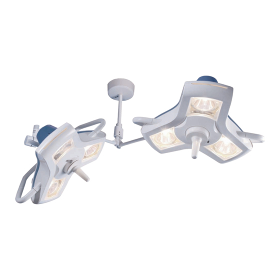
Burton AIM-50 Series Installation Manual
Double ceiling version
Hide thumbs
Also See for AIM-50 Series:
- Installation manual (20 pages) ,
- Operation & maintenance instructions manual (28 pages)

Related Manuals for Burton AIM-50 Series


Summary of Contents for Burton AIM-50 Series
- Page 1 AIM-50 ™ INSTALLATION MANUAL DOUBLE CEILING VERSION PERFORMANCE RELIABILITY VALUE The Right Light EXAMINATION...
- Page 3 A52 DC AIM-50™ Double Ceiling Version 240 V A53 DC AIM-50™ Double Ceiling Version 230 V This product was designed and assembled in the U.S.A. by BURTON MEDICAL PRODUCTS CORP. 21100 Lassen St. Chatsworth, CA 91311 U.S.A. Questions? Tel. (800) 444-9909...
-
Page 4: Table Of Contents
Table of Contents Table of Contents ............................2 Introduction ..............................3 Symbols Used in This Manual ......................4 Transportation and Storage ....................... 4 Safety Precautions ..........................4 Assembly Preparations ........................4 Support and Anchorage ........................5 Mounting Height ........................... 5 Range of Motion ........................... -
Page 5: Introduction
This product was designed and manufactured in the U.S.A. by: Burton Medical Products 21100 Lassen Street Chatsworth, CA 91311 U.S.A. Questions? Tel: (800) 444-9909 (818) 701-8700 Fax: (800) 765-1770 (818) 701-8725 www.burtonmedical.com Copyright © 2008 Burton Medical Products AIM-50™ Installation Manual − Double Ceiling Version 5000147 A01... -
Page 6: Symbols Used In This Manual
Symbols Used in This Manual Disregarding this instruction can present the risk of a serious or fatal WARNING injury. Disregarding this instruction can result in injury and damage to property. CAUTION Provides usage tips and useful information. IMPORTANT Transportation and Storage The following storage conditions apply: •... -
Page 7: Support And Anchorage
Distance from the floor to the pivot point of the spring arm. Cut the standard down tube (from the top) and drill three new holes. See instructions on page 17 Contact Burton to obtain a 20” or a 42” Down Tube. AIM-50™ Installation Manual − Double Ceiling Version 5000147 A01... -
Page 8: Range Of Motion
Range of Motion Figure 1: Range of motion shown for 9 ft ceiling and 16 inch down tube. AIM-50™ Installation Manual − Double Ceiling Version 5000147 A01... -
Page 9: Unpacking And Inspection
If a Shortage or Damage Occurs: 1. You, the receiver, not Burton, are responsible for filing any claim(s) with the delivering carrier within five (5) days after receipt of the shipment. 2. If damage or shortage occurs in transit, the delivering carrier is required by law to make notation of a shortage or damage. -
Page 10: Double Ceiling Version Installation
Double Ceiling Version Installation Ceiling Support Structure The engineer of record for the building shall provide a support structure designed to support weights and forces shown on the Equipment Anchorage Diagrams on page 19. When the support structure is in place the static inspection sheet on page 18 should be filled out and stored for future reference. -
Page 11: Installing The Down Tube
2. Mount the ceiling casting to the support structure. Make sure the hole in the ceiling casting above the terminal block aligns with the hole in the junction box. Use three (3) 3/8” bolts, plain washers, split lockwashers, and nuts in a triangular pattern. See Equipment Anchorage Diagrams on page 19 for details. - Page 12 Note: Illustration is for single ceiling version, so only one transformer and a smaller terminal block is shown. 2. Assemble the down tube by sliding it up the center hole in the ceiling casting. Position the tube so that the lower hole (A) in the down tube is matching to the upper hole (B) in the ceiling casting.
-
Page 13: Connecting Power
Connecting Power 1. The branch power from the wall switch should now be connected to the terminal block, which is pre-mounted on the ceiling casting. To insert wires into the terminal block use the technique shown on the illustration to the right. 2. - Page 14 3. Push the bell housing and the lock ring up until it covers the ceiling casting. Tighten the two set-screws on the lock ring using an Allen key (3/32 in / 2,4 mm). AIM-50™ Installation Manual − Double Ceiling Version 5000147 A01...
-
Page 15: Installing Wall Switch
Installing Wall Switch Note: There is one wall switch for each light head. Both wall switches must be supplied from one branch circuit. 115V / 120V version: Install the wall switch that is furnished with the product to a standard junction box per local codes. -
Page 16: Installing The Extender Arms With Spring Arm
Installing the Extender Arms With Spring Arm If the washer is not installed, the retaining ring can loosen over time. WARNING The light fixture can then fall and cause serious injury. Always install the Danger of injury washer with the retaining ring. The entire support system can become electrified if the power cables WARNING - are damaged at the plug. -
Page 17: Mounting The Light Heads
Mounting the Light Heads The spring arm, when pressed downwards, can spring upwards and result WARNING in injuries. During the installation of the light head, no one should be Danger of injury present within swiveling range of the spring arm. CAUTION Key must be properly installed to avoid safety hazard. - Page 18 6. After the connectors are mated, push the yoke into the spring arm. 7. Put the key (e) completely into the slot (a), so that the key is engaged into the yoke groove (h). See figure 4. Figure 5 8. Rotate the collar (c) 180 degrees as shown in figure 5. Before installing the brake screw (b), check the attachment of the light head by pulling and rotating it at the same time.
-
Page 19: Final Testing
Final Testing Turn the individual wall switches on to check proper operation. The arm system should swing easily within the range of motion as illustrated on page 6. Adjusting Arm Tension The spring inside the arm is pre-adjusted at the factory. If, however, the light head drifts up or down, please refer to the Operation &... -
Page 20: Static Inspection
Static Inspection NOTE: The static (structural) inspection must be carried out before installing the wall mount or ceiling casting. • The strength of the construction must be designed, checked and certified by a structural engineer. • The respective regional construction regulations that apply must be followed. •... -
Page 21: Equipment Anchorage Diagrams
Equipment Anchorage Diagrams Double Ceiling Version - Overview AIM-50™ Installation Manual − Double Ceiling Version 5000147 A01... - Page 22 Double Ceiling Version – Plan Ceiling AIM-50™ Installation Manual − Double Ceiling Version 5000147 A01...
- Page 24 BURTON MEDICAL 21100 Lassen Street Chatsworth, CA 91311 USA Phone: 800-444-9909, 818-701-8700 Fax: 800-765-1770, 818-701-8725 www.burtonmedical.com The Right Light...
Need help?
Do you have a question about the AIM-50 Series and is the answer not in the manual?
Questions and answers