Table of Contents
Advertisement
Quick Links
The material in this manual is for informational purposes only and is subject to change, without notice.
QuadTech assumes no responsibility for any error or for consequential damages that may result from the
misinterpretation of any procedures in this publication.
~ Product will be marked with this symbol (ISO#3684) when it is necessary for the user to refer
to the instruction manual in order to prevent injury or equipment damage.
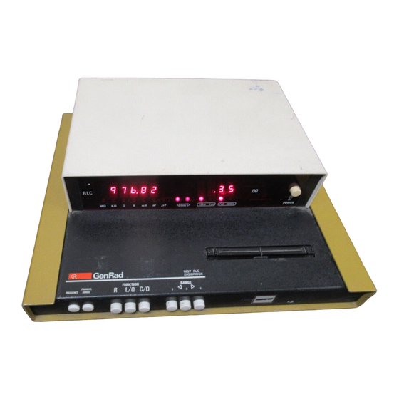
1657 RLC Digibridge®
®QuadTech, Inc., 1992
5 Clock Tower Place, 210 East
Maynard, Massachusetts, U.S.A. 01754
January, 1997
Tel. 978-461-2100
800-253-1230 (Sales)
800-253-1230 (Service)
Fax. 978-461-4295
Contents
Instruction Manual Changes
Specifications
Warranty
Introduction -Section 1
Installation -Section 2
Operation -Section 3
Theory -Section 4
Service and Maintenance -Section 5
Parts Lists and Diagrams -Section 6
Instruction Manual
Foun 1657-0120-07/B1
Advertisement
Table of Contents

Subscribe to Our Youtube Channel
Related Manuals for QuadTech 1657 RLC Digibridge


Summary of Contents for QuadTech 1657 RLC Digibridge
- Page 1 The material in this manual is for informational purposes only and is subject to change, without notice. QuadTech assumes no responsibility for any error or for consequential damages that may result from the misinterpretation of any procedures in this publication.
- Page 2 Fuse is 6/l0A, 250V, 3AG Type, Slow Blow. The 1657 is shipped with a standard U.S. power cord, QuadTech PN 4200-0300 (with Belden SPH-386 socket or equivalent, and 3 wire plug confonning to IEC 320) or an approved international cord set.
- Page 3 IEC 245 should be used. Page 3-2 -Paragraph 3.1 Basic Procedure, step a Power line switch for 115V or 230V operation has been removed, switching is automatic. Page 5-1 -Paragraph 5.2, Instrument Return Contacts for QuadTech are: Sales 800-253-1230 Service 800-253-1230...
- Page 4 Ranges: Pushbutton selection with automatic front-panel guidance. Three basic ranges Measurement Mode: Measures R series or parallel; L and Q series or parallel; C (best accuracy, see table) of 2 decades each, for each parameter. Automatic extensions and D series or parallel. All measurement modes are pushbutton selectable. to min and max, as tabulated.
-
Page 5: Service Policy
SERVICE POLICY QuadTech policy is to maintain product repair capability for a period of five (5) years after original shipment and to make this capability available at the then prevailing schedule of charges. - Page 6 Table of Contents...
-
Page 7: General Description
1.1 PURPOSE 1.2 GENERAL DESCRIPTION 1.3 CONTROLS, INDICATORS, AND CONNECTORS 1.4 ACCESSORIES 1.1 PURPOSE. in keeping with the long-life circuitry inside. Glass-epoxy The 1657 Digibridge digital impedance meter embodies circuit boards interconnect and support high-quality com use of a microprocessor and other LSI circuitry to ponents to assure years of dependability. - Page 8 1-2 INTRODUCTION...
- Page 9 INTRODUCTION 1-3...
- Page 10 1-4 INTRODUCTION...
-
Page 11: Unpacking And Inspection
The instrument is fitted with a power connector that is in conformance 2.1 UNPACKING AND INSPECTION. with the International Electrotechnical Commission publication 320. The 3 If the shipping carton is damaged, ask that the carrier's flat contacts are surrounded by a cylindrical plastic shroud that reduces the agent be present when the instrument is unpacked. - Page 12 This remote test fixture functions like the one supplied on the If your line voltage is in the higher range selectable by the line voltage Digibridge. True "Kelvin" connections are made at the points of contact switch, use a power cord of the proper rating (250 V, 15 A) that mates with the DUT leads.
-
Page 13: External Bias
P-(potential, low) = Black/white Notice that the 2 wires with red must connect to the same end of the I-(current, low) = Black DUT, through a coaxial tee if the DUT is a 2-terminal device; the 2 P+(potential, high) = Red/white wires labeled with black, connect to the other end, similarly. - Page 14 recommended. Connect across the power supply a bleeder resistor that b. Connect a suitable bias voltage source (see below) draws dc current at least as great as the peak measuring current (item 3 in series with the 1+ connection, basically as shown in above).
-
Page 15: Operation
OPERATION 3-1... -
Page 16: Basic Procedure
3.1 BASIC PROCEDURE. Figure 3-1. Notice that the 2 red tips must connect to the same end of the DUT. The For initial familiarization, follow this procedure care terminals with white bands are potential connections; with no bands, current fully. For details, refer to later paragraphs in Operation. terminals. - Page 17 3.3 FUNCTION AND RANGE SELECTIONS. 3.2 CONNECTION OF THE DUT. 3.3.1 Function Pushbuttons. 3.2.1 The Integral Test Fixture. The selection of the principal parameter to be measured is almost self- The test fixture provided on the front ledge of the Digi explanatory.
- Page 18 Each basic range is slightly more than 2 decades wide, from an R LC the high extension of the highest range, both ADJUST RANGE arrows are display of 01900, with an automatic decimal lighted (to indicate a useful "overrange" condition) . point change between the decades, to 19999.
- Page 19 Figure 3-2. R L C basic accuracy as a percent of reading. Heavy lines (solid and dotted) represent best choice of range. Range 2 is dotted. Notice that Land C scales above graph are for 120 Hz (*equally valid for 100 Hz) and the 2 below graph are for 1 kHz.
- Page 20 The logarithmic scales on these figures make it very easy to apply the specify with your results whether they are "parallel" or "series" and what the accuracy factors visually. For example, suppose a capacitor is being measured measurement frequency was. on range 2, both ADJUST RANGE lights are out, and the D display' is about Resistors, below about 1 kΩ: Series, 120 Hz (100 Hz).
- Page 21 3.5.4 Equivalent Series R for Capacitors. The total loss of a capacitor can be expressed in several ways, including D and "ESR." To obtain equivalent series resistance, one can measure directly (if D is high enough to permit the desired accuracy) or calculate. Direct Measurement.
- Page 22 a. Install an adaptor, GR 874-Q2, on each of the WARNING To minimize shock hazard, limit bias to 30 V. two coaxial connectors, Land H, of the capacitor. Bias voltage is present at connectors, test b. Connect cable branch G to the ground post of the "low" terminal fixtures and on capacitors under test.
- Page 23 4.1 INTRODUCTION. 4.2 PRINCIPAL FUNCTIONS. components in this instrument are three standard resistors 4.1 INTRODUCTION. and a quartz-crystal stabilized oscillator. There is no reactance 4.1.1 General. standard. For example, C and D are calculated by the microprocessor This instrument uses an unusual method of measurement, which is quite from the set of 8 voltage measurements and predetermined values of different from those used in previous impedance meters or bridges.
- Page 24 4-2 THEORY...
- Page 25 4.2.3 Sine-Wave Generation. Figure 4-4. 4.2.2 Frequency and Time Source. Figure 4-3. Starting with a digital signal at 256 times the selected A necessary standard for accuracy is the frequency of the test signal; and test frequency, the sinewave generator provides the test signal that drives a equally important are the generation of 4-phase references for detection and small but essential current through the DUT.
- Page 26 5.1 CUSTOMERSERVICE........................5-1 5.2 INSTRUMENT RETURN........................5-1 5.3 REPAIR AND REPLACEMENT OF PLUG-IN BOARDS..............5-1 5.4 PERFORMANCE VERIFICATION....................5-2 5.5 MINIMUM-PERFORMANCE STANDARDS..................5-2 5.6 DISASSEMBLY AND ACCESS....................... 5-9 507 PERIODIC MAINTENANCE......................5-11 5.8 TROUBLE ANALYSIS........................5-13 WARNING These servicing instructions are for use by qualified personnel only.
-
Page 27: Customer Service
all surfaces of the instrument. Insert fillers between pads and container to ensure 5.1 CUSTOMER SERVICE. a snug fit. Mark the box "Delicate Instrument" and seal with strong tape or metal Our warranty (at the front of this manual) attests the quality of bands. -
Page 28: Performance Verification
Verify performance as follows: 1. Instrument description: name and catalog and serial a. Set the line voltage switch, connect the power cord, numbers. Refer to front and rear panels. and depress the POWE R button. 2. Part number of board. Refer to the parts lists in this manual. (The b. -
Page 29: Minimum Performance Standards
For example, if your 1-kΩ standard is actually 1.005 kΩ, known to +/-0.1 %, Insignificant figures. The right-hand digit(s) of the display normally flicker then the acceptable readout is 1.005 +/-0.3%, i.e., 1.0020 (min) to 1.0080 (max) and change if they are not significant for the specified accuracy of the kΩ. - Page 30 5-4 SERVICE...
- Page 31 5.5.2 Resistance Measurement Accuracy. determ ination of cable capacitance. The corrected readout of capacitance a. Set the line voltage switch, connect the power is the actual display minus the cable capacitance. cord, and depress the POWER button. Allow 5 minutes for warm-up CAUTION (during which time steps b through f can be done) before accuracy Do NOT connect the 1417 capacitor without a...
- Page 32 box. (Be sure this is not strapped to G.) Connect cable tip G to G of the The difference between these 2 measurements is the corrected readout. resistance box and to the outer terminals of the capacitance box. For each other check, CB, CC, CD ..., a single measurement is sufficient.
- Page 33 The next step, removal of display board, is recommended (though not 5.6.1 Disassembly. Figures 5-1 through 5-6. absolutely necessary) before removal of the main circuit board. Use the following procedure for access to replaceable c. Remove the 2 support screws, at left and right, that hold the display parts and contact points used in trouble analysis.
- Page 34 d. Remove the ribbon cable (1657-0200) from power supply (at V-J1) Notice that it is possible to remove the main board with the display and main board (at C-J1). Notice that the connectors are symmetrical and board mounted on it, by this procedure: release all 8 front push buttons; reversible;...
- Page 35 Screw K must contact etched-circuit ground. A washer is supplied (under screw head) if necessary to do so. 5.6.2 Access. Figures 5-7 and 5-8. Interior locations that are important for trouble analysis are shown. Notice the clues to pin numbering; square pads on etched board are generally pin 1.
-
Page 36: Periodic Maintenance
b. Clean and check the 4 contact strips. Use a card wet with isopropyl 5.6.3 Reference Designations. alcohol for cleaning. Hold the board at an angle so that any drip falls away Refer to Section 6 for an explanation of these designations. from the circuits. -
Page 37: Trouble Anal Ysis
a mild glass cleaner, such as "Windex" (Drackett Products Co., Cincinnati, Display. A perpetually blank digit or decimal point may be caused by a Ohio). Do NOT use a paper towel; do NOT use enough liquid to drip or fault in the directly associated circuit on the display board. (Refer to run. - Page 38 5.8.2 Power Supply. Check the power supply (V assembly) if there is a massive failure (nothing works) or as a starting procedure in any thorough analysis. Refer to figures 5-8 and 6-10. NOTE If a power transistor (U1, U2, or U3) must be replaced, be sure to spread silicone grease (like Dow Corning compound no.
- Page 39 they will fit the socket directly.) Check at U12 pin 4 for a 1-kHz noisy sine wave, 0.4 V pk-pk. If this is verified but step g is not, fault is in U18. If neither is verified, reinstall U 18 and continue.
- Page 40 p. While monitoring U14 pin 2, push the FREQUENCY pushbutton and select 120 Hz, (or 100 Hz). Check that the monitored signal (which should always be 256 times the test frequency) is now 30720 Hz or 25600 Hz. Again push the FREQUENCY button to select "1 kHz."...
- Page 41 Also, the amplitudes of the staircases depend on the RANGE selected ga. If step g is not verified, check at the switch control terminals U40 pins 5,6, 12, 13 for the presence of digital and the impedance components of the DUT. The chosen conditions signals with logic high and low levels of +5 V and -8 V.
- Page 42 5-16 SERVICE...
- Page 43 aa. Provide reset pulses in either of 2 ways. Preferably, set up a pulse generator as follows: a. Look at the following control signals with a scope Source resistance: 50 Ω. and compare them with the timing diagram: Repetition rate (period): 1 s. PBST, at C-U33 pin 10;...
- Page 44 c. If the feedback signals are present, look at each of the following control signals and compare it with the timing diagram: (The first 4 signals have logic low and high levels of 0 and +5 V; the last 8 signals, -8 and +5V) PBST, at U33 pin 10;...
- Page 45 Parts Lists and Diagrams- Section 6 6.1 GENERAL ....6.2 REFERENCE DESIGNATIONS ..6 - 1 6 - 1 DIAGRAMS.
- Page 47 FRONT CFigure 6-l 1 _ Mftr Part No. Description den Rad Part Mftr Foot (4 required) each: 5260-2051 5260-2051 24655 Display panel ( 120 Hz) 1657-7001 1657-7001 24655 (or) Display panel (100 Hz) 1657-7002 1657-7002 24655 Switch actuator rod assembly 1657-2810 24655 1657-2810...
-
Page 48: Parts And Diagrams
FEDERAL SUPPLY CODE MANUFACTURERS Ref FMC Column in Parts From Defense Logistics Agency Microf icbe G S A - F S S H4-2 80894 66289 0 , 2 4 7 6018, 81030 6777, 16801 8 , 0 7 3 60626 66730 0 7 2 0 7 8 , 1 4 3...
Need help?
Do you have a question about the 1657 RLC Digibridge and is the answer not in the manual?
Questions and answers