Table of Contents
Advertisement
Quick Links
The material in this manual is for informational purposes only and is subject to change, without notice.
QuadTech assumes no responsibility for any error or for consequential damages that may result from the
misinterpretation of any procedures in this publication.
Voltage may be present on front and rear panel terminals. Follow all warnings in this manual when
operating or servicing this instrument. Substantial levels of energy may be stored in capacitive devices
!
Product will be marked with this symbol (ISO#3864) when it is necessary for the user to refer to
the instruction manual in order to prevent injury or equipment damage.
Product marked with this symbol (IEC417) indicates presence of direct current.
Product will be marked with this symbol (ISO#3864) when voltages in excess of 1000V are
present.
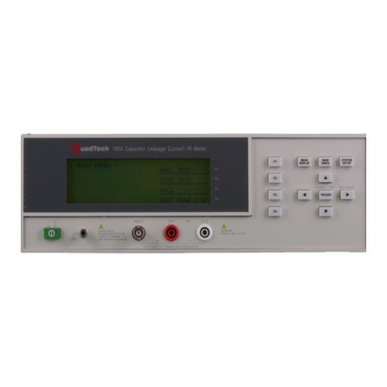
Capacitor Leakage Current/IR Meter
©QuadTech, Inc., 2004
5 Clock Tower Place, 210 East
Maynard, Massachusetts, U.S.A. 01754
October 2006
Telephone
Sales
Facsimile
Website
CAUTION
tested by this unit.
Instruction Manual
978-461-2100
800-253-1230
978-461-4295
www.quadtech.com
1855
Form
150767/A4
Advertisement
Table of Contents

Subscribe to Our Youtube Channel
Related Manuals for QuadTech 1855


Summary of Contents for QuadTech 1855
- Page 1 The material in this manual is for informational purposes only and is subject to change, without notice. QuadTech assumes no responsibility for any error or for consequential damages that may result from the misinterpretation of any procedures in this publication.
- Page 2 Page 2 of 76...
-
Page 3: Table Of Contents
Contents Warranty ........................5 Specifications ........................7 Accessories ........................11 Safety Precautions....................... 13 Condensed Operating Instructions..................15 Introduction - Section 1 Unpacking and Inspection..................19 Product Overview ....................19 Controls and Indicators .................... 20 1.3.1 Front Panel Controls and Indicators ............20 1.3.2 Rear Panel Controls and Connectors ............ - Page 4 Handler Pin Assignments for Compare Operation ........74 Service & Calibration - Section 4 General ........................75 Instrument Return ....................75 Calibration ....................... 75 4.3.1 1855 Verification Procedure ..............76 4.3.2 1855 Verification Data Sheet ..............76 Page 4 of 76...
-
Page 5: Warranty
SERVICE POLICY QuadTech’s service policy is to maintain product repair capability for a period of at least five (5) years after original shipment and to make this capability available at the then prevailing schedule of charges. - Page 6 Page 6 of 76...
-
Page 7: Specifications
Specifications Leakage Current Test: 0.001uA – 20.0mA Leakage Current: ±(0.3% + 0.005uA) Accuracy: 1.0V – 650V DC, 0.1V/Step Test Voltage: ±(0.5% + 0.2V) Voltage Accuracy: 0.5mA – 500mA, 0.5mA/Step for DCV ≤ 100V Test Current: 0.5mA – 150mA, 0.5mA/Step for DCV > 100V ±(3% + 0.05mA) Charge Current Accuracy: Insulation Resistance Test:... - Page 8 Specifications (Continued) General Features Automatic Sequence Test Test Types: Manual Step Test Correction for Lead Leakage Null: 1.0V – 650V DC (Voltage across DUT) Monitored Voltage (Vm): 0 – 999seconds in 1s/10s increments <100s; 100s increments >100s Charge Time: 0.2 – 999seconds in 0.1s increments <100s; 10s increments>100s Delay Time: 65 Watt Discharge Circuit Discharge:...
- Page 9 Installation Category I 90-125VAC 190-250VAC • • Power: 50 or 60Hz 400W max • • Instruction Manual Power Cable • • Supplied: Calibration Certificate Lead Set • • Description Catalog No. Ordering Information: Capacitor Leakage Current/IR Meter 1855 Page 9 of 76...
- Page 10 Page 10 of 76...
-
Page 11: Accessories
Accessories Accessories Included Item Quantity QuadTech P/N AC Power Cord 4200-0300 Power Line Fuse: 4A 250V SB for 115V operation 520149 Power Line Fuse: 2A 250V SB for 230V operation 520148 Test Leads: Banana to Alligator Clip & BNC to Alligator Clip... - Page 12 Page 12 of 76...
-
Page 13: Safety Precautions
Safety Precautions CAUTION The 1855 Capacitor Leakage Current/IR Meter can provide an output voltage of 650V DC to the device under test (DUT). Although the 1855 unit is a low voltage instrument, some devices (especially capacitors) can store charge when tested. If not discharged properly, these devices may cause serious hazards. - Page 14 Page 14 of 76...
-
Page 15: Condensed Operating Instructions
The 1855 Capacitor Leakage Current/IR Meter can be operated from a power source between 90- 125V or 190-250V AC at a power line frequency of 50 or 60Hz. The standard 1855 unit is shipped from QuadTech with a 4A fuse in place for AC 90-125V operation. (A 2A fuse is included for AC 190-250V operation). - Page 16 Condensed Operating Instructions (Continued) There are three main menus within the 1855 instrument software. Familiarize yourself with these menus prior to programming a test. Figure COI-1 illustrates the MEAS DISPLAY screen and lists the functions that can be accessed by pressing the [MAIN INDEX] and [SYSTEM SETUP] keys.
- Page 17 • Set test parameters (voltage, current, range, etc.) using the function & arrow keys. 2. Null After setting your test parameters, use the Null function of the 1855 instrument to zero the test leads. With no device connected, connect the appropriate cable to the front panel BNC/Banana connectors.
- Page 18 Condensed Operating Instructions (Continued) 3. Connection to Device under Test (DUT) Figure COI-3 illustrates the connection of the 1855 instrument to a DUT using the 1855-01 Lead Set. For Leakage Current, Insulation Resistance and Withstand Voltage Tests, the red alligator clip/BNC cable is connected between the silver INPUT terminal on the 1855 unit and the high side of the device under test.
-
Page 19: Unpacking And Inspection
Measurements can be made continuously or triggered with a programmable delay time up to 10 seconds. The 1855 comes standard with an RS-232 interface. An optional IEEE- 488 and Handler interface is also available. Voltage across the DUT can be monitored and displayed. -
Page 20: Controls And Indicators
Controls and Indicators 1.3.1 Front Panel Controls and Indicators Figure 1-2 illustrates the controls and indicators on the front panel of the 1855 Capacitor Leakage Current/IR Meter instrument. Table 1-1 identifies them with description and function. QuadTech 1855 Capacitor Leakage Current /IR Meter... -
Page 21: Rear Panel Controls And Connectors
1.3.2 Rear Panel Controls and Connectors Figure 1-3 illustrates the controls and connectors on the rear panel of the 1855 Capacitor Leakage Current/IR Meter instrument. Table 1-2 identifies them with description and function. 115V ~/230V~ RS232 WARNING: FOR CONTINUED PROTECTION... -
Page 22: Installation
An ESD mat is not a recommended test platform. 1.4.3 Power Requirements The 1855 can be operated from a power source of 90 to 125V AC or 190 to 250V AC. Power connection is via the rear panel through a standard receptacle. Before connecting the 3-wire power cord between the unit and AC power source, make sure the voltage selection switches on the rear panel (Figure 1-5) are in accordance with the power source being used. -
Page 23: Safety Inspection
Procedure for Changing an 1855 Instrument Fuse Unscrew the fuse cap on the rear panel of the 1855 and pull fuse holder outward. Once the fuse holder has been removed from the instrument snap the fuse from the holder and replace. -
Page 25: Terms And Conventions
Section 2: Operation Terms and Conventions Table 2-1: Measurement Unit Prefixes Multiple Scientific Engineering Symbol 10 15 1000000000000000 Peta 10 12 1000000000000 Tera 10 9 1000000000 Giga 10 6 1000000 Mega 10 3 1000 Kilo 10 -3 .001 milli 10 -6 µ... - Page 26 DUT: Device Under Test. (i.e. the product being tested). Ground: The base reference from which voltages are measured, nominally the same potential as the earth. Ground is also the side of a circuit that is at the same potential as the base reference. Insulation Resistance: Measures the total resistance between any two points separated by electrical insulation.
-
Page 27: Startup
Power is applied to the 1855 instrument by pressing the green power switch on the front panel to the ON (1 position). The 1855 unit should warm up for a period of at least 15 minutes prior to measurements being made. -
Page 28: System Configuration
2.3.3 System Configuration Prior to programming a test or measuring a device, set up the system controls of the 1855 instrument. To access the system controls, press [SYSTEM SETUP] then press [F3] = [SYSTEM CONFIG]. Table 2-2 lists the contents of SYSTEM CONFIG. -
Page 29: Test Parameter
2.3.3.1 Test Parameter The 1855 Capacitor Leakage Current/IR Meter can function as a Leakage Current tester or as an Insulation Resistance meter. The instrument default setting is L.C. To change the function of the 1855 Capacitor Leakage Current/IR Meter press [SYSTEM SETUP] then [SYSTEM CONFIG] The box next to TEST PARAMETER is highlighted. -
Page 30: Alarm Mode
The trigger delay is the amount of time between the activation of a trigger (via IEEE, Handler or front panel) and the 1855 making the measurement. The delay time can be programmed from 0000 to 9995 seconds. The instrument default value is 0000 seconds. To change the TRIGGER DELAY press [SYSTEM SETUP], [SYSTEM CONFIG] and the down arrow [⇓] until the box... -
Page 31: Handler Mode
2.3.3.7 Handler Mode The handler interface mode can be set to CLEAR or HOLD. The instrument default setting is CLEAR. When set to CLEAR, the handler interface will clear the last test result prior to each subsequent measurement. When set to HOLD, the handler interface will hold the last test result until the next measurement is made and displayed. -
Page 32: Rs232 Baud Rate
< MEAS DISPLAY: SEQ. TEST > TEST V. 1.0V Lc : 3.65 mA C.C. 0.5mA RANGE Vm = 0.0V CHARGE TEST DISCHARGE NEXT PAGE 1/2 NOTE: Key Lock is disabled when the 1855 instrument is shut down. Page 32 of 76 Interface... -
Page 33: Line Frequency
The range dwell is the amount of time the instrument holds at the programmed test voltage before the 1855 makes the measurement. The range dwell is in addition to, and occurs after, the charge time. The range dwell can be programmed from 0 to 9.9 seconds. The instrument default value is 0 seconds. -
Page 34: Average
2.3.3.15 Average The 1855 instrument can make many measurements then display the average based on what average number was selected. The range is 1 – 8 and the instrument default setting is 1. To change the number to average press [SYSTEM SETUP], [SYSTEM CONFIG] and the down arrow [⇓] until the box next to AVERAGE is highlighted, then press [F1] = DIGIT UP to... -
Page 35: Main Index
MAIN INDEX Within the 1855 instrument’s MAIN INDEX are the Sequence Test, Step Test, Null, Withstand Voltage Test and Compare functions. To access these functions, press [MAIN INDEX] and the display should look as shown in Figure 2-3. < MAIN INDEX >... -
Page 36: Step Test
For maximum measurement accuracy it is recommended that the NULL function be performed on the 1855 instrument after power up, any time the test parameters are changed and any time the test leads or fixture is changed. - Page 37 Connection of test leads for Null function: QuadTech 1855 Capacitor Leakage Current /IR Meter MEAS MAIN SYSTEM <MEAS. DISPLAY: NULL> DISPLAY INDEX SETUP LC : CHARGE/TEST DISCHARGE Press TRIGGER to start ... TRIGGER CHARGE TEST DISCHARGE INPUT OPEN No DUT Connected for NULL function...
-
Page 38: Test
Withstand Voltage is the voltage at which the product’s insulation begins to break down. There are however many definitions for Withstand Voltage. The 1855 instrument and this manual use the WV terminology from the EIAJ RC-2364A standard, “Test Methods of Electrode Foils for Aluminum Electrolytic Capacitors”. -
Page 39: Compare
2.4.5 Compare The Compare function provides the capability to set an upper and/or lower limit for a leakage current or insulation resistance test and to display Pass/Fail with the measured result. To access the Compare function, press [MAIN INDEX] and [F4] = NEXT PAGE 1/2 then press [F2] = COMPARE. - Page 40 To set up and display PASS/FAIL on the MEAS DISPLAY screen, use the COMPARE function. Example: Parameter = Leakage Current. Upper Limit = 15mA, Lower Limit = 0. < MAIN INDEX > SEQ. TEST STEP TEST NULL NEXT PAGE 1/2 <...
-
Page 41: Meas Display
MEAS DISPLAY The 1855 instrument’s stand-by display is the MEAS DISPLAY. After power has been applied to the instrument and it cycles quickly through the information screen, the instrument reverts to the MAIN INDEX. Once [SEQ. TEST] or [STEP TEST] is selected the instrument enters the MEAS DISPLAY. -
Page 42: Test Voltage
Figure 2.11 illustrates the two pages of parameters that can be programmed within the MEAS DISPLAY for a SEQUENCE TEST. Figure 2.12 illustrates the two pages of parameters that can be programmed within the MEAS DISPLAY for a STEP TEST. The two tests have the similar programmable parameters with the exception of Charge Time, Range Dwell and Trigger. -
Page 43: Range
LEFT arrow [⇐] key: decrease current in 1mA increments. 2.5.3 Range The 1855 instrument’s measurement range can be selected as AUTO or HOLD. The instrument current measurement ranges are 20mA, 2mA, 200uA, 20uA and 2uA. In MEAS DISPLAY, press [F3] = RANGE so that the A box is highlighted*. The instrument default setting is A (Auto Range). -
Page 44: Charge Time
2.5.4 Charge Time The charge time can be programmed from 0 to 999seconds. In MEAS DISPLAY press [F4] = NEXT PAGE 1/2. Press [F1] = CHG T so that the 0 s box is highlighted. Use the up or down arrow keys to in/decrease the charge time by base-10 second increments. -
Page 45: Speed
NEXT PAGE 2/2 2.5.7 Trigger In the Step Test only, the 1855 instrument can be triggered manually, internally or externally. In MEAS DISPLAY, press [F4] = NEXT PAGE 1/2 and then press [F1] = TRIGGER so that the INT box is highlighted. Press [F1] = TRIGGER to change the trigger. The instrument default setting is INT (internal trigger). -
Page 46: Rated Withstand Voltage (Vf)
2.5.8 Rated Withstand Voltage (Vf) In the W.V. Test only, the rated withstand voltage (Vf) can be programmed from 1.00V to 650V. In MEAS DISPLAY press [F1] = Vf so that the 1.00 V box is highlighted. Use the up arrow or down arrow keys to in/decrease the voltage in multi-V increments. -
Page 47: Maximum Charge Time (Chg Tend)
2.5.10 Maximum Charge Time (CHG Tend) In the W.V. Test only, the charge time can be programmed from 5 to 600seconds. In MEAS DISPLAY press [F4] = CHG Tend so that the 5 s box is highlighted. Use the up or down arrow keys to in/decrease the charge time by 10 second increments. -
Page 48: Connection To Device Under Test
Connection to Device under Test Figure 2-13 illustrates the connection of the 1855 instrument to a DUT using the 1855-01 Lead Set. For Leakage Current, Insulation Resistance and Withstand Voltage Tests, the red alligator clip/BNC cable is connected between the silver INPUT terminal on the 1855 unit and the high side of the device under test. -
Page 49: Measurement Procedure
Upon completion of the test the output voltage is terminated and the display shows the test result. CAUTION: Before touching the DUT or the 1855 instrument, make sure all capacitive devices have been fully discharged. Interface Page 49 of 76... -
Page 51: Rs-232 Interface
The 1855 instrument comes standard with an RS232 Interface for remote operation. Connection is through the black/silver 9-pin connector labeled ‘RS232’ on the rear panel of the 1855 instrument. Figure 3-1 illustrates the designation of the pins on the RS232 connector. The connection cable must be a ‘straight through’... -
Page 52: Rs232 Commands
Refer to paragraph 2.3.3.10. Setting the Baud Rate is done in the SYSTEM CONFIGURATION function under SYSTEM SETUP settings: • From the MEAS DISPLAY, press [SYSTEM SETUP] • Press [F3] = SYSTEM CONFIG. • Press [⇓] = until the box next to BAUD RATE is highlighted. •... -
Page 53: Ieee-488 Interface
24-pin connector labeled ‘IEEE-488 INTERFACE’ on the rear panel of the 1855 instrument. This interface can be used to connect a system containing a number of instruments and a controller in which each meets IEEE Standard 488.2 (Standard Digital Interface for Programmable Instrumentation). - Page 54 Table 3-1 lists the IEEE-488 Interface pin designations by pin number, signal name and pin function. Bus and driver information is also listed. Table 3-1: IEEE-488 Interface Pin Designations Bus Driver Signal Function Name Number 3 States Low State: “Data is Available” and valid on DI01 through DI08 Open NRFD...
-
Page 55: Ieee-488 Interface Function Codes And Messages
Refer to paragraph 2.3.2 for more information. The default setting for the IEEE address is 17. Table 3-2 defines the IEEE-488 interface codes and their function. Table 3-3 defines the IEEE- 488 interface messages the 1855 instrument responds to and their function. Table 3-2: IEEE-488 Interface Functions Code... - Page 56 Table 3-4 lists the IEEE-488 interface commands the 1855 instrument accepts to set or query a parameter value. Paragraphs 3.2.3 through 3.2.5 detail the function, format, return value and description of the IEEE-488 commands. Table 3-4: IEEE-488 Commands Command Name...
-
Page 57: Ieee-488 Interface Commands
Figure 3-3 illustrates the programming commands accepted by the IEEE-488 interface of the 1855 instrument. The commands are written in tabular format as a single reference to view all the commands. The command format and examples are detailed in paragraphs 3.2.4 – 3.2.5. - Page 58 Tabular Format IEEE-488 Commands – continued ABORt WVTest SOURce VOLTage CURRent CONFigure TEND CHGTEND MEASure STATe? VTerminate? TEnd? TRIGger IMMediate SOURce DELay EDGE SYSTem BEEPer IMMediate STATe ALARm LFRequency HANDler CONTrast RANGEDwell AVErage PRESet ERRor? Figure 3-3b: IEEE-488 Commands Page 58 of 76 Interface...
-
Page 59: Ieee-488 Command Format
3.2.4 IEEE-488 Command Format The IEEE-488 commands are configured in Root format. There are six levels of the instruction from top to bottom. Follow the specific path (as illustrated in Figure 3.3) to configure a specific command. The colon at the beginning of each line denotes that all line signals are root. Use a colon (:) to separate levels. -
Page 60: Ieee-488 Commands - Detailed
3.2.5 IEEE-488 Commands - Detailed The IEEE commands listed in Figure 3-3 are detailed in paragraphs 3.2.5.1 – 3.2.5.39 including command, parameter, return value, function, and description. Note: Numerical data is transferred via one of three methods: integer format, fixed decimal format or floating point decimal format. - Page 61 3.2.5.4 CALC:LIM:BEEP:STAT Instruction: CALC:LIM:BEEP:STAT Parameter: {OFF⏐ON⏐0⏐1} Return Value: {0⏐1} Function: Set or query the status of the beeper. Description: OFF (0) Beeper sound is set to OFF ON (1) Beeper sound is set to ON 3.2.5.5 CALC:LIM:FAIL? Instruction: CALC:LIM:FAIL? Parameter: {0 (FAIL)⏐1 (PASS)} Return Value: {0⏐1}...
- Page 62 3.2.5.9 CALC:LIM:ONOF Instruction: CALC:LIM:ONOF Parameter: {0⏐1⏐2⏐3} Return Value: {0⏐1⏐23⏐3} Function: Set or query the status of the Compare function. Description: Compare function is OFF Compare Upper Limit is ON Compare Lower Limit is ON Compare Upper and Lower Limits are ON 3.2.5.10 CALC:NULL:[IMM] Instruction:...
- Page 63 3.2.5.13 DISP:⏐ WVT, L CT, null, main, system⏐ Instruction: DISP: WVT DISP: LCT DISP: NULL DISP: MAIN DISP: SYSTem Parameter: None Return Value: None Function: Set the Display to WV Mode, L CT mode, null, main or system mode. Description: Set the Display to WV Mode 3.2.5.14 LCT:SOUR:VOLT...
- Page 64 3.2.5.17 LCT:CONF:SPE Instruction: LCT:CONF:SPE Parameter: {FAST⏐MEDIUM⏐SLOW} Return Value: {FAST⏐MEDIUM⏐SLOW} Function: Set or query the Measurement Speed. Description: FAST 18 measurements/second MEDIUM 14 measurements/second SLOW 7 measurements/second 3.2.5.18 LCT:CONF:RANG Instruction: LCT:CONF:RANG Parameter: {<range>⏐MIN⏐MAX} Return Value: {<range>} Function: Set or query the measurement range for the LC Test. Description: 20mA 200uA...
- Page 65 3.2.5.21 LCT:CONF:DWEL Instruction: LCT:CONF:DWEL Parameter: {<numeric value>⏐MIN⏐MAX} Return Value: {<numeric value>} Function: Set or query the dwell time for the LC Test. Description: <numeric value> 0.2 – 999seconds 0.2seconds 999seconds 3.2.5.22 LCT:MEAS:STAT? Instruction: LCT:MEAS:STAT? Parameter: None Return Value: {CHG⏐TEST⏐DCHG} Function: Query the test status of the LC Test.
- Page 66 3.2.5.25 LCT:MEAS:LC? Instruction: LCT:MEAS:LC? Parameter: None Return Value: {Measured value} in <NR3> format Function: Query the LC measurement value. Description: LC measurement value 3.2.5.26 LCT:MEAS:VMON? Instruction: LCT:MEAS:VMON? Parameter: None Return Value: {Measured value} in <NR3> format Function: Query the value of the monitored voltage (voltage across DUT). Description: VMON value 3.2.5.27...
- Page 67 3.2.5.29 WVT:CONF:TEND Instruction: WVT:CONF:TEND Parameter: {<numeric value>⏐MIN⏐MAX} Unit: seconds Return Value: {Measurement Time} in <NR3> format Function: Set or query the measurement time for the WV Test. Description: <numeric value> 30 – 600seconds 30seconds 600seconds 3.2.5.30 WVT:CONF:CHGTEND Instruction: WVT:CONF:CHGTEND Parameter: {<numeric value>⏐MIN⏐MAX} Unit: seconds...
- Page 68 3.2.5.33 WVT:MEAS:TE? Instruction: WVT:MEAS:TE? Parameter: None Return Value: {Measurement Time} in <NR3> format Function: Query the total Measurement Time of the WV Test (Tr + Test Time). Description: <numeric value> 30 – 600seconds 3.2.5.34 TRIG[:IMM] Instruction: TRIG[:IMM] Parameter: None Return Value: None Function: Initiate the Trigger function.
- Page 69 3.2.5.38 SYST:BEEP[:IMM] Instruction: SYST:BEEP[:IMM] Parameter: None Return Value: None Function: Set the beeper to sound immediately. 3.2.5.39 SYST:BEEP:STAT Instruction: SYST:BEEP:STAT Parameter: {OFF (0)⏐ON, LOW (1)⏐ON, HIGH (2)} Return Value: {0⏐1⏐2} Function: Set the loudness of the beeper. Description: Turn Beeper OFF Set Beeper sound to LOW Set Beeper sound to HIGH 3.2.5.40...
- Page 70 3.2.5.43 SYST:CONT Instruction: SYST:CONT Parameter: {<numeric value>} Return Value: {Contrast} in <NR1> format Function: Set or query the contrast of the display. Description: <numeric value> 1-16 3.2.5.44 SYST:RANGED Instruction: SYST:RANGED Parameter: {<numeric value>⏐MIN⏐MAX} Return Value: {Dwell Time} in <NR3> format Function: Set or query the range dwell time.
-
Page 71: Error Messages
3.2.6 Error Messages Table 3-6 lists the Error Messages for the IEEE-488 interface of the 1855 instrument. In response to the command “SYSTem:ERRor?”, the 1855 unit responds with the error message number and an error message string of up to 80 characters in length. -
Page 72: Handler Interface
Handler Interface There is an available Handler interface for the 1855 instrument as illustrated in Figure 3-4. [The IEEE-488 and HANDLER interfaces come together as an optional accessory]. Connection to the Handler interface is through the blue 24-pin connector labeled HANDLER on the rear panel of the 1855 instrument. -
Page 73: Trigger
Figure 3-5: Trigger Output Signals The output lines of the 1855 Handler interface are open collector drivers that pull each signal line to a low voltage, signal ground when the signal is active (true). Each external line should be pulled up (with a resistor) to a positive voltage between 5V and 24V. The pull-up resistor must limit the current to <... -
Page 74: Handler Pin Assignments For Compare Operation
3.3.2 Handler Pin Assignments for Compare Operation Table 3-7 lists the pin assignments when the handler interface on the 1855 instrument is performing a Compare operation. The device under test is being compared against a standard of known value. High and low limits can be defined as absolute value or percent value. -
Page 75: General
Shipments sent collect cannot be accepted. Calibration Calibration of the 1855 Capacitor Leakage Current/IR Meter is completed at the factory and includes a NIST calibration certificate. Verification of the instrument is recommended on an annual basis. Accurate operation of the 1855 instrument is confirmed using the 1855-TP Test Procedure. -
Page 76: 1855 Verification Procedure
Data Sheet. If the calibrated values for the standards used do not have an uncertainty of 4 times better than the specified accuracy of the 1855 the uncertainty of the standard should be added to the specified accuracy of the 1855.
Need help?
Do you have a question about the 1855 and is the answer not in the manual?
Questions and answers