Table of Contents
Advertisement
Advertisement
Table of Contents

Related Manuals for Thermal Care Oiltherm RO


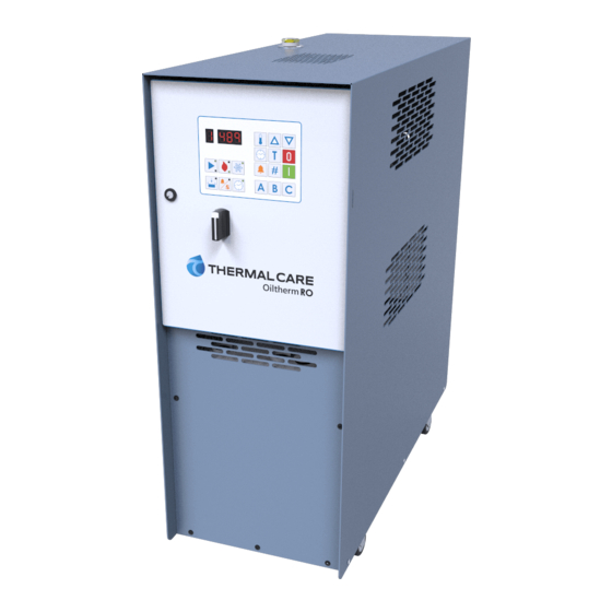
Summary of Contents for Thermal Care Oiltherm RO
-
Page 3: Table Of Contents
Table of Contents Foreword ..........................................1 Safety Guidelines ........................................1 Pre-Installation ........................................2 Receiving Inspection ......................................2 Unit Storage ..........................................2 Installation - Mechanical ....................................2 Foundation ..........................................2 Unit Location .......................................... 2 Rigging ............................................2 Fluid Distribution Piping ....................................2 Installation - Electrical ...................................... - Page 4 Controller Control Fault Logic ..................................8 Vacuum Option Cool-Down (Vac units only) ............................8 Start-up ............................................. 9 Step 1 – Connect Main Power ..................................9 Step 2 – Connect Oil Lines ....................................9 Step 3 – Connection Cooling Source ................................9 System Fill Water Chemistry Requirements ............................
-
Page 5: Foreword
Foreword General Mandatory Action The temperature control unit is a packaged unit that typically includes a fluid pump, electric immersion Wear Eye Protection heater, and temperature control valve in a cabinet. The purpose is to provide circulation and temperature control of a cooling fluid. Wear Protective Gloves This manual is to serve as a guide for installing, operating, and maintaining the equipment. -
Page 6: Pre-Installation
CAUTION: The equipment will exceed 70 dBA sound damages be reported within 15 days of receipt of pressure at 1 meter distance and 1 meter elevation the equipment. In addition, notify our Customer when operating. Wear ear protection as required for Service Department and they will provide assistance personal comfort when operating or working in close with preparing and filing freight damage claims,... -
Page 7: Installation - Electrical
the unit. Proper insulation of chilled process fluid (452 – 442) x 100 / 452 = 2.2 % piping is crucial to prevent condensation. The This exceeds the maximum allowable of 2%. formation of condensation adds a substantial heat load to the cooling system. There is a terminal block for main power connection to the main power source. -
Page 8: Controller Operation
Controller Operation Stop To stop the unit press the Stop button. When the unit is stops, the status display and the last digital display on the right will display a dot. WARNING: Stopping the unit without cooling the oil in the reservoir can lead to potential user injury during servicing of the unit. -
Page 9: Decrease
Displaying Day of the Week Decrease Press and release the Date & Time button twice to display the internal clock timer day of the week. The Pressing the Decrease button decreases the value of day of the week will display for 5 seconds. If no other the set point, deviation alarm, and timer settings buttons are pressed for 5 seconds the display will when those adjustment features are active. -
Page 10: Setting Start Time
in the above examples. Release all buttons after Examples of days of week displays selecting the timer status. If no other buttons are Monday (timer off) pressed for 5 seconds the timer status is set and display will return to the actual temperature. Monday (time on) Setting Start Time Tuesday (timer off) -
Page 11: Setting Deviation Alarm Temperature
Setting Deviation Alarm Temperature required to adjust temperatures or timer functions. To change the deviation alarm temperature press the The password remains in memory even if the power Deviation Alarm button and release and use the is disconnected. Increase and Decrease button to change the degrees of deviation from the set point temperature at which Entering or Changing Password the deviation alarm will activate. -
Page 12: Pump Status Indicator
Press the Off button to clear the password. The Automatic Cool-Down Prior to Stop display shows the following. The unit features an automatic cool-down function that ensures the unit and the fluid cools down to a Example of password deleted, no password entered safe temperature prior to stopping the unit for maintenance or repair. -
Page 13: Start-Up
Start-up phase sequencing will cause damage to components. Check the phasing prior to applying power. The proper sequence is “ABC.” If the phasing Every unit is factory set to deliver oil in accordance is incorrect, open the main power disconnect and with the standard operating specifications for that switch two line leads on the main power terminal particular unit. - Page 14 poisonous, easy to handle, widely available, and Table 1 - Fill Water Chemistry Requirements inexpensive in most industrialized areas. Water Characteristic Quality Limitation When using water as a heat transfer fluid it is Alkalinity (HCO 70-300 ppm important to keep it within certain chemistry limits to Aluminum (Al) Less than 0.2 ppm avoid unwanted side effects.
-
Page 15: Step 4 - Fill With Heat Transfer Oil
Step 4 – Fill with Heat Transfer Oil show the Set Point temperature in the display. If no other buttons are pressed for 5 seconds, the display Fill the unit with heat transfer oil suitable for will return to the actual temperature. continuous operation at 575°F. -
Page 16: Preventive Maintenance
Preventive Maintenance contactors, starters, and controls. Check for loose or frayed wires. Once the unit is in service, we suggest following the Check the incoming voltage to make sure it is maintenance procedures as closely as possible. The within 10% of the design voltage for the importance of a properly established preventive temperature control unit. -
Page 17: General Troubleshooting
General Troubleshooting Problem Possible Cause Remedy Main fuses blown Replace blown fuses The unit does not start after Motor defective Contact factory connection, tank filling, and Reset tripped Reset pressing the On button Control circuit breaker tripped Reset Check incoming power supply, check and Voltage on two of the phases only Motor buzzes after pressing the replace blown fuse... -
Page 18: Drawings & Charts
Drawings & Charts Figure 1 – Pump Curve (60 Hz) - Page 19 Figure 2 – Cooling Capacity...
- Page 20 Figure 3 –High Voltage Wiring Diagram...
- Page 21 Figure 4 – Low Voltage Wiring Diagram...
- Page 22 Figure 5 – Control Board Details...
- Page 23 Figure 6 – Heating Element Details...
- Page 24 Figure 7 – Principles of Operation Diagram (Standard Units) From process To process Cooling water in Cooling water out Pump Tank Level switch Temperature sensor Microprocessor control 10. Heat exchanger 11. Heating element 12. Overflow 13. Expansion tank 14. Solenoid valve for cooling 15.
- Page 25 Figure 8 – Principles of Operation Diagram (Units with Vacuum Option) From process To process Cooling water in Cooling water out Pump Tank Level switch Temperature sensor Microprocessor control 10. Heat exchanger 11. Heating element 12. Overflow 13. Expansion tank 14.
- Page 26 Notes...
- Page 28 New Equipment Sales Customer Service Parts Department 5680 W. Jarvis Ave. Niles, IL 60714 • 847-966-2260 info@thermalcare.com 847-966-2260 847-966-9358(fax) 847-966-2636 847-966-8560 847-966-9358(fax) • • • www.thermalcare.com info@thermalcare.com service@thermalcare.com tcparts@thermalcare.com RO IOM 00...
Need help?
Do you have a question about the Oiltherm RO and is the answer not in the manual?
Questions and answers