Table of Contents
Advertisement
Advertisement
Table of Contents

Subscribe to Our Youtube Channel
Related Manuals for Thermal Care Vactherm RV


Summary of Contents for Thermal Care Vactherm RV
-
Page 3: Table Of Contents
Table of Contents Foreword ..........................................1 Safety Guidelines ........................................1 Pre-Installation ........................................2 Receiving Inspection ......................................2 Unit Storage ..........................................2 Installation - Mechanical ....................................2 Foundation ..........................................2 Unit Location .......................................... 2 Rigging ............................................2 Fluid Distribution Piping ....................................2 Installation - Electrical ...................................... - Page 4 Controller Control Fault Logic ..................................8 Draining the Mold ........................................ 8 Start-up ............................................. 8 Step 1 – Connect Main Power ..................................9 Table 1 - Fill Water Chemistry Requirements ..........................10 Table 2 – Recommend Glycol Solutions ............................10 Step 3 – Start the Unit....................................... 10 Step 4 –...
-
Page 5: Foreword
Foreword General Mandatory Action The temperature control unit is a packaged unit that typically includes a fluid pump, electric immersion Wear Eye Protection heater, and temperature control valve in a cabinet. The purpose is to provide circulation and temperature control of a cooling fluid. Wear Protective Gloves This manual is to serve as a guide for installing, operating, and maintaining the equipment. -
Page 6: Pre-Installation
CAUTION: The equipment will exceed 70 dBA sound damages be reported within 15 days of receipt of pressure at 1 meter distance and 1 meter elevation the equipment. In addition, notify our Customer when operating. Wear ear protection as required for Service Department and they will provide assistance personal comfort when operating or working in close with preparing and filing freight damage claims,... -
Page 7: Installation - Electrical
the unit. Proper insulation of chilled process fluid (452 – 442) x 100 / 452 = 2.2 % piping is crucial to prevent condensation. The This exceeds the maximum allowable of 2%. formation of condensation adds a substantial heat load to the cooling system. There is a terminal block for main power connection to the main power source. -
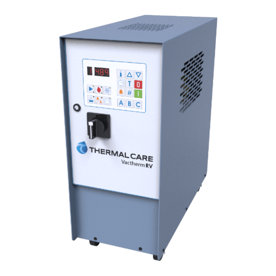
Page 8: Controller Operation
Controller Operation CAUTION: Stopping the unit without cooling the water in the reservoir can lead to potential user injury during servicing of the unit. In order to allow Figure 1 – Control Panel the water in the reservoir to be cooled automatically during shut down, depress the Temperature Adjust button and the Password ‘C’... -
Page 9: Displaying Pump Running Hours
Displaying Pump Running Hours and immediately use the Increase and Decrease Press the Date & Time button and release and buttons to set the current day of the week as follows. immediately press the Start button to display the pump running hours. The pump running hours will Releasing all buttons sets the day to the one shown display for 5 seconds. -
Page 10: Setting Timer Stop Time
Setting Timer Stop Time Examples of days of week displays To change the timer stop time press the Date & Time button and release, press the Timer On/Off Monday (timer off) button and release, press the Timer On/Off button Monday (time on) again and release. -
Page 11: Setting Deviation Alarm Temperature
Setting Deviation Alarm Temperature The password remains in memory even if the power To change the deviation alarm temperature press is disconnected. the Deviation Alarm button and release and use the Increase and Decrease button to change the degrees Entering or Changing Password of deviation from the set point temperature at which To enter or change a password, use the following the deviation alarm will activate. -
Page 12: Pump Status Indicator
Example of password deleted, no password entered Controller Control Fault Logic Alarm Indication Condition Tank Low Level Low Level Alarm indicator light on Temperature display flashing Press the On button to start the unit. The set Alarm horn on and X1 output powered point temperature can occur without the need Temperature Temperature Deviation Alarm indicating light on... -
Page 13: Step 1 - Connect Main Power
WARNING: This equipment contains hot water or and cumulative pressure rating of the maximum coolant under pressure. Accidental release of hot water pump pressure and the unit fill fluid pressure. or coolant under pressure can cause personal injury and or property damage. NOTE: A cooling source inlet filter ships loose in the crate with the unit. -
Page 14: Step 3 - Start The Unit
Unwanted Side Effects of Improper Water Quality Table 2 – Recommend Glycol Solutions Corrosion Chilled Water Temperature Percent Glycol By Volume • Scale 50°F (10°C) Not required • Fouling • 45°F (7.2°C) Biological Contamination • 40°F (4.4°C) 10 % 35°F (1.7°C) 15 % Cooling Water Chemistry Properties 30°F (-1.1°C) -
Page 15: Step 6 - Adjusting The Vacuum
the current Set Point and then immediately used the Once a Month Increase or Decrease buttons to change the Set Repeat items 1 through 3 listed above and continue Point until the desired temperature displays. Once with the following. the desired Set Point displays, release all buttons. After 5 seconds, the display will return to the actual With the main power shut off, check the temperature and the new set point is active. -
Page 16: General Troubleshooting
General Troubleshooting Problem Possible Cause Remedy Main fuses blown Replace blown fuses Motor defective Contact factory The unit does not start after connection, tank filling, and pressing the On button Reset tripped Reset Control circuit breaker tripped Reset Check incoming power supply, check and Voltage on two of the phases only Motor buzzes after pressing the On button replace blown fuse... -
Page 17: Charts And Drawings
Charts and Drawings Figure 1 – Pump Performance (60 Hz) - Page 18 Figure 2 – Cooling Capacity...
- Page 19 Figure 3 –High Voltage Wiring Diagram...
- Page 20 Figure 4 – Low Voltage Wiring Diagram...
- Page 21 Figure 5 – Control Board Details...
- Page 22 Figure 6 – Heating Element Details...
- Page 23 Figure 7 – Principle of Operation From mold To mold Cooling water in Cooling water out Pump Tank Level sensor Temperature sensor Microprocessor control 10. Heat exchanger 11. Heating element 12. Overflow pipe 13. Solenoid valve for water filling 14. Solenoid valve for cooling 15.
- Page 24 Notes...
- Page 25 Notes...
- Page 26 Notes...
- Page 28 New Equipment Sales Customer Service Parts Department 5680 W. Jarvis Ave. Niles, IL 60714 • 847-966-2260 info@thermalcare.com 847-966-2260 847-966-9358(fax) 847-966-2636 847-966-8560 847-966-9358(fax) • • • www.thermalcare.com info@thermalcare.com service@thermalcare.com tcparts@thermalcare.com RV IOM 00...
Need help?
Do you have a question about the Vactherm RV and is the answer not in the manual?
Questions and answers