Table of Contents
Advertisement
Advertisement
Table of Contents

Related Manuals for Thermal Care Aquatherm RQE


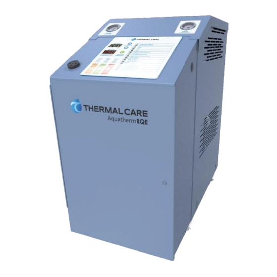
Summary of Contents for Thermal Care Aquatherm RQE
-
Page 3: Table Of Contents
Table of Contents Foreword ..........................................1 Safety Guidelines ........................................1 Pre-Installation ........................................2 Receiving Inspection ....................................... 2 Unit Storage ........................................2 Installation - Mechanical ....................................2 Foundation .......................................... 2 Unit Location ........................................2 Rigging ..........................................2 Fluid Distribution Piping ....................................2 Installation - Electrical ...................................... - Page 4 Page Intentionally Blank...
-
Page 5: Foreword
Foreword General Mandatory Action The temperature control unit is a packaged unit that typically includes a fluid pump, electric immersion Wear Eye Protection heater, and temperature control valve in a cabinet. The purpose is to provide circulation and temperature control of a cooling fluid. Wear Protective Gloves This manual is to serve as a guide for installing, operating, and maintaining the equipment. -
Page 6: Pre-Installation
CAUTION: The equipment will exceed 70 dBA sound damages be reported within 15 days of receipt of pressure at 1 meter distance and 1 meter elevation the equipment. In addition, notify our Customer when operating. Wear ear protection as required for Service Department and they will provide assistance personal comfort when operating or working in close with preparing and filing freight damage claims,... -
Page 7: Installation - Electrical
condensation adds a substantial heat load to the This exceeds the maximum allowable of 2%. cooling system. There is a terminal block for main power connection The importance of properly sized piping cannot be to the main power source. The main power source overemphasized. -
Page 8: Controller Operation
Controller Operation The temperature control unit includes a controller to perform all control functions directly from the front panel. When Control Power is applied, the controller Figure 1 – Standard Controller User Interface initiates a diagnostic test of each indicating light and display segment that temporarily lights them sequentially. - Page 9 Table 1 - Controller Operating Buttons Button Description of Operation Start Pressing the Start button initiates a vent sequence. The vent sequence removes air to prevent improper operation and premature heater failure. When initiated, the vent sequence opens the cooling valve for to allow air to escape, after 30 seconds it runs the pump for 30 seconds while the cooling valve is open to remove any remaining air from the system.
- Page 10 Table 2 - Temperature Displays Display Description of Operation Set Point The Set Point display normally shows the set point temperature. A decimal point in the lower right corner of this display indicates the temperature unit of measure is set to °F, no decimal point indicates the temperature unit of measure is set to °C. See the Menu Program section to change the temperature scale units of measure.
- Page 11 Table 3 – Operating Lights (continued) Light Description of Operation Remote Heat/Cool The Remote Heat/Cool light is on and yellow when this option is enabled. This feature allows the heating and cooling to (Optional) be turned on and off by remote contact closures. Switching a contact from open to close activates the heat or cool function assigned to the contact.
-
Page 12: Program Menu
Program Menu To change an item, press the Display/Program button until the item code displays in the Process Access to the program menu is password protected display. Pressing the Alarm Reset button and to prevent unintended alteration to the program Display/Program button at the same time will settings and parameters. -
Page 13: Seal Saver Sequence Initiation
Table 5 – Program Menu Items (continued) Item Default Item Name Range Code Valve Display units F or C High deviation alarm limit 5 to 100 degrees above set point Integral time 1 to 800 Low deviation alarm limit 5 to 100 degrees below set point Low pressure bypass enabled Disabled (DIS) or Enabled (EnA) Panel Temperature Alarm... -
Page 14: Spi Communications (Optional)
SPI Communications (Optional) Units ordered with this option will have this feature activated at the factory. Use the program menu Several members of SPI: The Plastics Industry Trade Communication Type function as shown in Table 5 Association defined a communications standard for to activate or deactivate this function. -
Page 15: Modbus Rtu (Optional)
Modbus RTU (Optional) The Modbus RTU option provides a RS-485 communications port for Modbus RTU communications. Note the Modbus Parity = None, Stop Bits = 1, and default Baud Rate = 9,600. Table 7 - ModBus Option Parameters Register Description Read/Write Format Notes... -
Page 16: Start-Up
Table 7 – Modbus Option Parameters Register Description Read/Write Format Notes 8016 High Setpoint Limit Temperature (°C) Floating Point 8018 Supply Temperature Retransmit Range Low (°C) Floating Point 8020 Supply Temperature Retransmit Range High (°C) Floating Point 8022 Low Temperature Safety – User Set (°C) Floating Point 8024 High Temperature Safety –... -
Page 17: Step 1 - Connecting Main Power
Step 1 – Connecting Main Power System Fill Water Chemistry Requirements The properties of water make it ideal for heat Connect main power properly ensuring it matches transfer applications. It is safe, non-flammable, non- the voltage shown on the nameplate of the unit. poisonous, easy to handle, widely available, and Check the electrical phase sequence prior to start- inexpensive in most industrialized areas. -
Page 18: Step 3 - Initial Unit Operation
Step 3 – Initial Unit Operation Table 8 - Fill Water Chemistry Requirements Water Characteristic Quality Limitation Enter the set point temperature. Refer to the Control Panel Operation section for further information. Alkalinity (HCO 70-300 ppm Aluminum (Al) Less than 0.2 ppm Start the unit by pressing the Start button on the Ammonium (NH Less than 2 ppm... -
Page 19: Preventive Maintenance
Preventive Maintenance Once the unit is in service, we suggest following the maintenance procedures as closely as possible. The importance of a properly established preventive maintenance program cannot be overemphasized. Taking the time to follow these simple procedures will result in substantially reduced downtime, reduced repair costs, and an extended useful lifetime for the unit. -
Page 20: Troubleshooting
Troubleshooting Problem Possible Cause Remedy Alternating Poor water flow Check connectors and increase size if necessary. If there are overheating and a large number of hoses and/or they are long, try to overcooling or shorten hose runs and use as large of a hose as possible to rapid cycling from minimize water-circuit pressure drop. - Page 21 Notes...
- Page 22 Notes...
- Page 24 New Equipment Sales Customer Service Parts Department 5680 W. Jarvis Ave. Niles, IL 60714 • 847-966-2260 info@thermalcare.com 847-966-2260 847-966-9358(fax) 847-966-2636 847-966-8560 847-966-9358(fax) • • • www.thermalcare.com info@thermalcare.com service@thermalcare.com tcparts@thermalcare.com RQE IOM 00...
Need help?
Do you have a question about the Aquatherm RQE and is the answer not in the manual?
Questions and answers