Advertisement
Quick Links
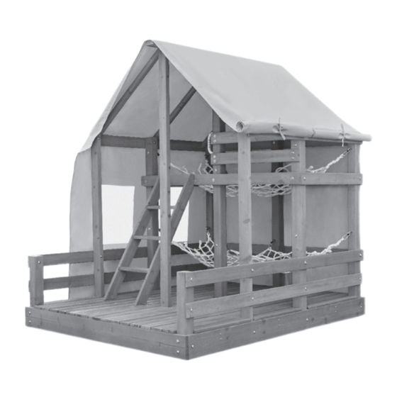
56
Glamping House
OWNER'S MANUAL &
ASSEMBLY INSTRUCTIONS
ITEM: 657511C3 Little Tikes® • 2180 Barlow Road, Hudson, Ohio 44236 • 1-800-321-0183
THIS PRODUCT IS INTENDED FOR USE BY CHILDREN FROM AGES 3 TO 10.
CAPACITY: 4 USERS MAXIMUM - WEIGHT LIMIT: 110 lbs. (50 kg) PER CHILD
FOR OUTDOOR USE.
For the latest instruction manual, to register your product, or to order replacement parts, please visit:
www.littletikes.com
Please keep this manual as it contains important information.
© The Little Tikes Company, an MGA Entertainment
company.
LITTLE TIKES® is a trademark of Little Tikes in the U.S.
and other countries. All logos, names, characters,
likenesses, images, slogans, and packaging
appearance are the property of Little Tikes.
Printed in U.S.A. · 0421-0-C3
At minimum, two people are required
to lift the boxes that contain the parts
for this unit and to assemble this unit.
Little Tikes Consumer Service
2180 Barlow Road
Hudson, Ohio 44236 U.S.A.
1-800-321-0183
1
Advertisement

Related Manuals for MGA Entertainment Real Wood Glamping House 657511C3


Summary of Contents for MGA Entertainment Real Wood Glamping House 657511C3
- Page 1 For the latest instruction manual, to register your product, or to order replacement parts, please visit: www.littletikes.com Please keep this manual as it contains important information. © The Little Tikes Company, an MGA Entertainment Little Tikes Consumer Service company. 2180 Barlow Road LITTLE TIKES®...
- Page 2 Step 85: Congratulations, this completes the assembly of the Glamping House. If any parts are damaged or missing, please contact consumer service before returning the item. LITTLE TIKES® 1-800-321-0183 8 a.m. - 8 p.m. EST 7 DAYS A WEEK 1. Have your receipt handy. 2.
-
Page 3: Important Safety Information
Step 83: IMPORTANT SAFETY INFORMATION Attach the Light Box Strip (DL01) to the Tarp using the (9) ties attached to the Tarp. WARNING: INSTRUCTIONS FOR SAFE USE • To reduce the risk of serious injury or death, you MUST read and WARNING: follow these instructions before assembly and before use. -
Page 4: Vertical Height
IMPORTANT SAFETY INFORMATION Step 81: RECOMMENDED SURFACING Remove the Light Box Screw and Light Box Cover from the Light Box (DL01). Insert WARNING: (3) fresh 1.5V A A (LR6) Alkaline Batteries. Make sure the positive and the negative To reduce the likelihood of serious head injuries, install shock-absorbing protective surfacing under and around this unit. The protective surfacing should be ends face the proper direction as indicated inside the battery compartment. - Page 5 Step 79: IMPORTANT SAFETY INFORMATION Secure the Tarp to the Rail Board (C06) and Roof Board (C11) using (3) Screws (C5). CRITICAL FALL HEIGHT Maximum critical fall height is 6 feet (2m). The obstacle-free safety zone which requires safety surfacing is a perimeter that extends 6 feet (2 meters) out from the unit and at least 12 feet (3.7 meters) in front and back of to-fro swings.
- Page 6 Step 77: INFORMATION ON PLAYGROUND SURFACING MATERIALS Place the Tarp (PB01) over the Glamping House Assembly as shown. The following information is from the United States Consumer Product Safety Commission’s Information Sheet for playground surfacing material. Additional Information can be found here: https://www.cpsc.gov/s3fs-public/324.pdf SECTION 4 OF THE CONSUMER PRODUCT SAFETY COMMISSION’S OUTDOOR HOME PLAYGROUND SAFETY HANDBOOK Select Protective Surfacing...
-
Page 7: Maintenance
Step 75: IMPORTANT SAFETY INFORMATION Hammer (2) Ground Stakes (DD01) into the ground next to the Tower Legs (L05) and ONLY REPLACE DAMAGED OR DEFECTIVE PRODUCT PARTS ACCORDING TO THE MANUFACTURER’S INSTRUCTIONS. (L01) as shown. Secure each Ground Stake using (1) Screw (B1). MAINTENANCE Twice a month during play season: At the beginning of each play season:... - Page 8 Step 73: Attach (1) Handle (LS01) to the Tower Leg (L03) using (2) Washers (LS01) and (2) Screws • Use only size “AA” (LR6) alkaline batteries (3 required). (LS01). Place (1) Cap over each Screw. • Charging of rechargeable batteries should only be done under adult supervision. Note: You may need a Rubber Mallet.
-
Page 9: Limited Warranty
Step 71: LIMITED WARRANTY Attach (2) Roof Supports (J1) to the Roof Board (C11) using (2) Screws (C3). Attach the The Little Tikes Company makes fun, high quality toys. We warrant to the original purchaser that this product is free of defects in Roof Supports to Tower Legs (C01) and (L03) using (2) Screws (C4). - Page 10 Step 69: TOOLS Attach (1) Roof Board (C11) to the Tower Legs (C01), (L03), and (L04) using (3) Screws TOOLS YOU WILL NEED (NOT INCLUDED) (B1). Ensure that the end with the overhang is placed over the Tower Leg (C01). To complete this procedure, you will need a Power Drill, a Hammer, a Rubber Mallet, a Metric Socket Wrench Set, a Level, a Square, an Adjustable Wrench, a Tape Measure, a Ladder (not pictured), and (3) AA Batteries.
-
Page 11: Parts List
Step 67: PARTS LIST Stand and align the Ladder Assembly with the Rail Board (C13). (1) Baseboard - C03 (4) Bracket - G1 (1) Block (1) Baseboard - C04 (2) Baseboard - C05 (2) Floor Support- C20 Step 68: (11) Floor Support- C10 Secure the Ladder Assembly to the Glamping House Assembly using (4) Brackets (G1) and (24) Screws (C1). - Page 12 Step 65: PARTS LIST CONTINUED Attach (1) Rear Board (C19) to the Ladder Assembly using (4) Screws (C2). (2) Floorboard- C16 (3) Floorboard- C17 (4) Ground Stake- DD01 (1) Floorboard- C18 Step 66: Turn the Ladder Assembly over. (1) Handle- LS01 (2) Hammock- DW01 (1) Left Upright- H4 (3) Ladder Rung- H2...
- Page 13 Step 63: PARTS LIST CONTINUED Align (1) Right Upright (H3) with (1) Left Upright (H4). Note the location of the angled edges. (4) Rail Board- C08 (1) Rail Board- C13 (1) Roof Board- C11 (6) Roof Support- J1 Step 64: Insert (3) Ladder Rungs (H2) into the grooves of the Left and Right Uprights.
- Page 14 PARTS LIST CONTINUED Step 61: Lay out and evenly space (7) Floorboards (C14) as shown. Attach the Floorboards using (84) Screws (C2). (1) Tower Leg- L03 (1) Tower Leg- L04 (2) Tower Leg- L05 (2) Wall Rail Board- C12 Step 62: (2) Wall Rail Board- C09 The following steps will guide you through the Ladder Assembly.
- Page 15 ASSEMBLY INSTRUCTIONS Step 59: Attach (1) Floorboard (C15) to the Floor Supports (C20), (H1), and (C10) using (6) Screws (C2). Step 1: This procedure will assist you with assembling the Glamping House. Step 2: To complete this procedure, you will need a Power Drill, a Hammer, a Rubber Mallet, a Metric Socket Wrench Set, a Level, a Square, an Adjustable Wrench, a Tape Measure, a Ladder, and (3) AA Batteries.
- Page 16 Step 57: Step 7: Attach (1) Floorboard (C17) to the Floor Supports (C10) and (H1) using (6) Screws (C2). The following steps will guide you through the Glamping House Assembly. Step 58: Step 8: Attach (1) Floorboard (C16) to the Floor Supports (C20), (H1), and (C10) using (4) Screws (C2).
- Page 17 Step 9: Step 55: Insert (2) Nuts (A-2) into (1) Tower Leg (L04) as shown. Orient the Tower Leg as shown Attach (1) Floorboard (01) to the Baseboards (C03) and (C04) and the Floor Supports with the (7) large predrilled holes facing up. (H1) and (C20) using (6) Screws (C2).
- Page 18 Step 11: Step 53: Lay out (2) Tower Legs (L05) and (1) Tower Leg (L04) as shown. Ensure the previously Attach (1) Floorboard (C16-1) to the Floor Supports (C10) using (4) Screws (C2). installed Nuts on the Tower Legs face the correct direction. Ensure that the small pilot holes on the (2) Tower Legs (L05) face the outside.
- Page 19 Step 51: Step 13: Attach (1) Floorboard (C16) to the Floor Supports (C10) using (4) Screws (C2). Attach (3) Rail Boards (C06) to the Tower Legs using (9) Nuts (A1) and (9) Bolts (A1). Ensure that the predrilled holes on the Rail Boards are closer to the Baseboard (C04). Step 14: Step 52: Stand the Tower Leg Assembly upright.
- Page 20 Step 49: Step 15: Attach (1) Floor Support (H1) to the Baseboards (C05) using (4) Screws (C4). Ensure Attach (2) Baseboards (C05) to the Tower Legs (L05) using (2) Bolts (A-2). Ensure that that the Floor Support is aligned with the top edge of the Baseboards. the Baseboards are placed with the measurements between the bolt holes oriented as shown and that the small predrilled holes are towards the top of the Baseboards.
- Page 21 Step 47: Step 17: Attach (1) Floor Support (H1) to the Baseboards (C05) using (4) Screws (C4). Ensure Insert (2) Nuts (A-2) into (1) Tower Leg (L03) as shown. Orient the Tower Leg as shown that the Floor Support is aligned with the top edge of the Baseboards. with the (4) small predrilled holes facing up.
- Page 22 Step 45: Step 19: Attach (1) Floor Support (C10) to each Tower Leg (C02) and Tower Leg (C01) using Lay out (1) Tower Leg (L02), (1) Tower Leg (L03), and (1) Tower Leg (L02-1) as shown. (12) Screws (C2). Ensure the previously installed Nuts on the Tower Legs face the correct direction and that the (4) small predrilled holes on the Tower Legs are facing up.
- Page 23 Step 21: Step 43: Attach (1) Rail Board (C13) to the Tower Legs using (3) Nuts (A3) and (3) Bolts (A3). Attach (1) Floor Support (C10) to each Tower Leg (L05) and Tower Leg (L04) using (12) Screws (C2). Step 44: Step 22: Attach (1) Floor Support (C10) to Tower Legs (L02-1), (L03), and (L02) using (12) Stand the Tower Leg Assembly upright.
- Page 24 Step 41: Step 23: Attach (1) Wall Rail Board (C12) to Tower Legs (L03) and (L02-1) using (4) Screws (B1). Attach the Tower Leg Assembly to the Baseboard (C05) using (1) Bolt (A-2). Ensure the Rail Board and Floor Support are oriented as shown. Step 42: Step 24: Attach (1) Wall Rail Board (C12) to Tower Legs (L03) and (L02-1) using (4) Screws (B1).
- Page 25 Step 25: Step 39: Insert (2) Nuts (A-2) into (1) Tower Leg (C01) as shown. Orient the Tower Leg as shown Attach (1) Rail Board (C07) to the Tower Legs using (3) Nuts (A1) and (3) Bolts (A1). with the (2) large predrilled holes facing up. Ensure the edges of the Rail board are ush with the edges of the Tower Legs.
- Page 26 Step 27: Step 37: Attach (1) Floor Support (C20) to Tower Leg (C01) using (2) Bolts (A-2). Attach the Attach (1) Rail Board (C07) to the Tower Legs using (3) Nuts (A1) and (3) Bolts (A1). Floor Support (C20) to Tower Legs (C02) using (4) Screws (B1). Ensure the edges of the Rail board are ush with the edges of the Tower Legs.
- Page 27 Step 29: Step 35: Attach the Tower Leg Assembly to the Rail Board (C08) using (1) Nut (A1) and (1) Bolt Secure the Baseboard (C05) to the Tower Legs using (3) Bolts (A-2). (A1). Attach the Tower Leg Assembly to the Baseboard (C05) using (1) Bolt (A-2). Ensure the Floor Support is oriented as shown.
- Page 28 Step 31: Step 33: Attach (1) Baseboard (C03) to the Tower Legs (L01) using (4) Bolts (A-2). Attach the Tower Leg Assembly to the Rail Board (C08) using (1) Nut (A1) and (1) Bolt (A1). Attach the Tower Leg Assembly to the Baseboard (C05) using (1) Bolt (A-2). Step 32: Step 34: Stand the Tower Leg Assembly upright.
Need help?
Do you have a question about the Real Wood Glamping House 657511C3 and is the answer not in the manual?
Questions and answers