Table of Contents
Advertisement
Quick Links
Advertisement
Table of Contents

Related Manuals for Microchip Technology MCP401XEV


Summary of Contents for Microchip Technology MCP401XEV
- Page 1 MCP401XEV Evaluation Board User’s Guide © 2010 Microchip Technology Inc. DS51888A...
- Page 2 Endurance, TSHARC, UniWinDriver, WiperLock and ZENA are trademarks of Microchip Technology Incorporated in the U.S.A. and other countries. SQTP is a service mark of Microchip Technology Incorporated in the U.S.A. All other trademarks mentioned herein are property of their respective companies.
-
Page 3: Table Of Contents
Chapter 1. Product Overview 1.1 Introduction ..................... 5 1.2 What is the MCP401XEV Evaluation Board? ..........5 1.3 What the MCP401XEV Evaluation Board Kit Includes ........6 Chapter 2. Installation and Operation 2.1 Introduction ..................... 7 2.2 Features ......................8 2.3 Getting Started .................... - Page 4 MCP401XEV Evaluation Board User’s Guide NOTES: © 2010 Microchip Technology Inc. DS51888A-page 4...
-
Page 5: Preface
• Customer Support • Document Revision History DOCUMENT LAYOUT This document describes how to use the MCP401XEV Evaluation Board as a development tool to emulate and debug firmware on a target board. The manual layout is as follows: • Chapter 1. “Product Overview” – Important information about the MCP401XEV Evaluation Board. - Page 6 MCP401XEV Evaluation Board User’s Guide CONVENTIONS USED IN THIS GUIDE This manual uses the following documentation conventions: DOCUMENTATION CONVENTIONS Description Represents Examples Arial font: ® Italic characters Referenced books MPLAB IDE User’s Guide Emphasized text ...is the only compiler... Initial caps...
- Page 7 Preface RECOMMENDED READING This user’s guide describes how to use the MCP401XEV Evaluation Board. Other useful documents are listed below. The following Microchip documents are available and recommended as supplemental reference resources. AN1080 Application Note, “Understanding Digital Potentiometer Resistor Variations”, DS01080...
- Page 8 MCP401XEV Evaluation Board User’s Guide DOCUMENT REVISION HISTORY Revision A (January 2010) • Initial Release of this Document. © 2010 Microchip Technology Inc. DS51888A-page 8...
-
Page 9: Chapter 1. Product Overview
MCP401XEV EVALUATION BOARD USER’S GUIDE Chapter 1. Product Overview INTRODUCTION This chapter provides an overview of the MCP401XEV Evaluation Board and covers the following topics: • What is the MCP401XEV Evaluation Board? • What the MCP401XEV Evaluation Board kit includes... -
Page 10: What The Mcp401Xev Evaluation Board Kit Includes
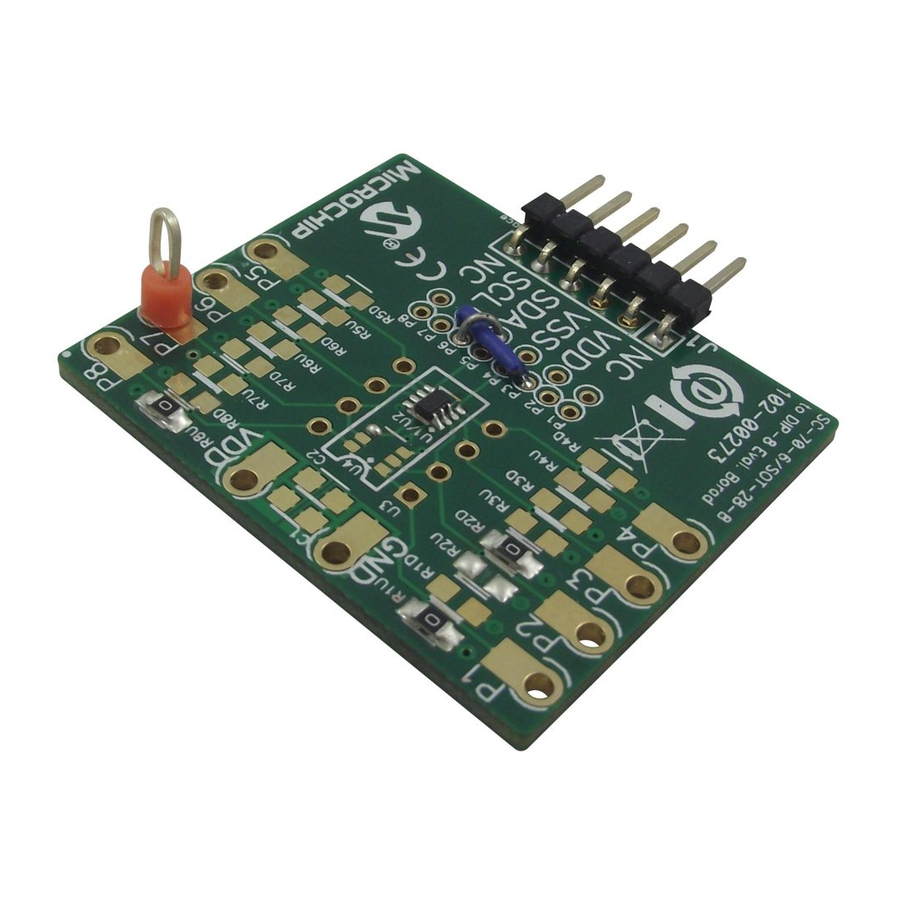
MCP401XEV Evaluation Board User’s Guide 0 Ω 0 Ω 0 Ω FIGURE 1-1: MCP401XEV Evaluation Board Using the SC70EV Evaluation Board (MCP40D18 installed in U1). WHAT THE MCP401XEV EVALUATION BOARD KIT INCLUDES This MCP401XEV Evaluation Board kit includes: • MCP401XEV Evaluation Board •... -
Page 11: Chapter 2. Installation And Operation
Serial Analyzer. The PICkit Serial Analyzer is available separately (order number: DV164122). The MCP401XEV Evaluation Board is a minimum configuration for the device. As well as the device, other desired passive components (resistors and capacitors) and connection posts may be installed. -
Page 12: Features
MCP401XEV Evaluation Board User’s Guide FEATURES The MCP401XEV Evaluation Board has the following features: • MCP40D18-103AE/LT is installed (I C address of 7Ch) • 0Ω resistors connect MCP40D18 VDD and VSS signals to the appropiate Power or Ground plane (see Figure 2-2) •... -
Page 13: Getting Started
2.4.1 The Hardware Figure 2-2 shows the component layout of the MCP401XEV Evaluation Board. This is a small four-layer board (1.43" x 1.255" (36.322 mm x 31.877 mm)). There are ten connection points/pads that can use either through-hole or surface-mount connector posts. - Page 14 MCP401XEV Evaluation Board User’s Guide DIP-8 PICkit (1, 2) SC70-6 Serial Interface (1, 2) SOT-23-8 Requires blue wire jumpering to connect the PICkit Interface to the selected device. = 0Ω (1, 2) SOT-23-6 = 0Ω Magenta text indicates installed components. Does not include two “blue wire”...
- Page 15 0 Ω Two Blue Wire Jumpers to connect PICkit Serial interface to device pins 1x6 Male Header, with 90° right angle FIGURE 2-2: MCP401XEV Evaluation Board Component Placement Using the SC70EV Evaluation Board (Top). © 2010 Microchip Technology Inc. DS51888A-page 15...
- Page 16 MCP401XEV Evaluation Board User’s Guide TABLE 2-1: INSTALLED PASSIVE COMPONENTS Component Description Comment R1U, R8U 0Ω SMT 805 Pull-up resistor 0Ω SMT 805 Pull-down resistor MCP40D18-103AE/LT 10 kΩ, Device I C Slave Address = 7Ch Test Point - through hole connector...
-
Page 17: Configuring The Pickit Serial Analyzer
Hardware. When starting the PICkit Serial Analyzer for the 1st time, some setup questions may be asked. If you have any questions, please refer to the PICkit Serial Analyzer documentation, available at www.Microchip.com/PICkitSerial. FIGURE 2-3: PICkit Serial Main Window at Startup. © 2010 Microchip Technology Inc. DS51888A-page 17... - Page 18 MCP401XEV Evaluation Board User’s Guide We need to select the PICkit Serial Analyzer GUI to be in I C Master mode. Figure 2-4 shows how to select the proper mode. Select PICkit Serial Analyzer -> Select Communications Mode -> I2C Master menu item (make sure the I2C Master item is checked).
- Page 19 Now we need to configure the mode that we have selected. Figure 2-5 shows how to select the communications mode. Select PICkit Serial Analyzer -> Configure Communications Mode menu item. This will open a new window. FIGURE 2-5: PICkit Serial Main Window at Startup. © 2010 Microchip Technology Inc. DS51888A-page 19...
- Page 20 MCP401XEV Evaluation Board User’s Guide Figure 2-6 shows the Configure Communications Mode window. Ensure that your window options and settings are the same as in this window, and then select the “Save Changes” button. FIGURE 2-6: PICkit Serial Configure Communications Mode Window.
- Page 21 Now we are going to create some custom scripts to match the MCP40D18 read and write commands. To open the Script Builder window, select the Communications -> Script -> Script Builder menu item (see Figure 2-7). FIGURE 2-7: PICkit Serial - Script Bulider Menu Selection. © 2010 Microchip Technology Inc. DS51888A-page 21...
- Page 22 MCP401XEV Evaluation Board User’s Guide This will open the Script Builder window (Figure 2-8). In this window we see five Example I C Master Scripts. We will use the ReadAddrA8 and WriteAddrA8 Example Script Files to create our User I C Master Scripts.
- Page 23 C Slave Address + Read/Write bit Number of Bytes that will be written (R/W bit = 0) Data Byte #1 Data Byte #2 Note 1: Function depends on devices I C Protocol Format. FIGURE 2-9: Example Write Script. © 2010 Microchip Technology Inc. DS51888A-page 23...
- Page 24 MCP401XEV Evaluation Board User’s Guide Double clicking on the ReadAddrA8 Example I2CM Script will load the Script Details. Figure 2-10 shows what the values mean in the Script Details. These values are hex numbers. The first value (02h) is the number of bytes that will be written. The second byte is the C Slave address (A8h) of the device with the Read/Write bit forced to ‘0’...
- Page 25 C:\Program Files\Microchip\PICkit Serial Analyzer Data value to write Device I C Address Command Code = “00” (in Hex) to Wiper = 7F (in hex) + Read/Write bit (= ‘0’) FIGURE 2-11: MCP40D18 Write Script File. © 2010 Microchip Technology Inc. DS51888A-page 25...
- Page 26 MCP401XEV Evaluation Board User’s Guide To create the read script for the MCP40D18, double click on the ReadAddrA8 script in the “Example I2CM Scripts” column. This loads the script (see Figure 2-10) into the “Script Detail” column. Modify the script details so that it looks like Figure 2-12. Then, in the “Script Name”...
-
Page 27: Mcp40D18Ev Demo Steps
If at any time during script execution, an error message is generated in the transaction window, it is good practice to reset the PICkit Serial Analyzer (PKSA). The PKSA can be reset using the “Reset” toolbar icon. Verify that subsequent script operations do not generate errors. © 2010 Microchip Technology Inc. DS51888A-page 27... - Page 28 MCP401XEV Evaluation Board User’s Guide Data value to write to Wiper FIGURE 2-13: MCP40D18 Write Script File - Updating Wiper Value. FIGURE 2-14: MCP40D18 Read Script File. © 2010 Microchip Technology Inc. DS51888A-page 28...
- Page 29 Data value writen to Wiper register FIGURE 2-15: MCP40D18 Transaction Windows 1 and 2. Data value read from Wiper register Data value written to Wiper register FIGURE 2-16: MCP40D18 Transaction Windows 3 and 4. © 2010 Microchip Technology Inc. DS51888A-page 29...
- Page 30 MCP401XEV Evaluation Board User’s Guide 2.6.1 The SC70EV PCB and Supported Digital Potentiometers Table 2-3 shows the current Digital Potentiomers that are supported by the SC70EV PCB. TABLE 2-3: SC70EV PCB SUPPORTED DIGITAL POTENTIOMETERS Device SC70 SOT-23 Comment MCP4012 —...
-
Page 31: Appendix A. Schematic And Layouts
• Board - Layer 3 Power Plane • Board - Bottom Silk, Trace and Pads SCHEMATICS AND PCB LAYOUT Board - Schematic shows the schematic of the MCP401XEV Evaluation Board. The layer order is shown in Figure A-1. Top Layer... -
Page 32: Board - Schematic
MCP401XEV Evaluation Board User’s Guide BOARD - SCHEMATIC © 2010 Microchip Technology Inc. DS51888A-page 32... -
Page 33: Board - Top Trace, Silk And Pads
Schematic and Layouts BOARD - TOP TRACE, SILK AND PADS © 2010 Microchip Technology Inc. DS51888A-page 33... -
Page 34: Board - Bottom Trace & Pads
MCP401XEV Evaluation Board User’s Guide BOARD - BOTTOM TRACE & PADS © 2010 Microchip Technology Inc. DS51888A-page 34... -
Page 35: Board - Layer 2 Ground Plane
Schematic and Layouts BOARD - LAYER 2 GROUND PLANE © 2010 Microchip Technology Inc. DS51888A-page 35... -
Page 36: Board - Layer 3 Power Plane
MCP401XEV Evaluation Board User’s Guide BOARD - LAYER 3 POWER PLANE © 2010 Microchip Technology Inc. DS51888A-page 36... -
Page 37: Board - Bottom Silk, Trace And Pads
Schematic and Layouts BOARD - BOTTOM SILK, TRACE AND PADS © 2010 Microchip Technology Inc. DS51888A-page 37... - Page 38 MCP401XEV Evaluation Board User’s Guide NOTES: © 2010 Microchip Technology Inc. DS51888A-page 38...
-
Page 39: Appendix B. Bill Of Materials (Bom)
22-28-8062 Electronics Corp ® TEST POINT PC MULTI PURPOSE ORG Keystone Electronics 5013 Note 1 Microchip Technology Inc. 104-00273 (Note 3) ® R1U, R8U, RES 0.0 OHM 1/8W 5% 0805 SMD Panasonic - ECG ERJ-6GEY0R00V 7-Bit Single I2C™ (with Command Code) Microchip Technology Inc. -
Page 40: Worldwide Sales And Service
Tel: 66-2-694-1351 Tel: 408-961-6444 Fax: 86-29-8833-7256 Fax: 66-2-694-1350 Fax: 408-961-6445 China - Xiamen Toronto Tel: 86-592-2388138 Mississauga, Ontario, Fax: 86-592-2388130 Canada Tel: 905-673-0699 China - Zhuhai Fax: 905-673-6509 Tel: 86-756-3210040 Fax: 86-756-3210049 12/30/09 © 2010 Microchip Technology Inc. DS51888A-page 40... - Page 41 Mouser Electronics Authorized Distributor Click to View Pricing, Inventory, Delivery & Lifecycle Information: Microchip MCP401XEV...
Need help?
Do you have a question about the MCP401XEV and is the answer not in the manual?
Questions and answers