
Related Manuals for Comelit Secur HUB


Summary of Contents for Comelit Secur HUB
- Page 1 TECHNICAL MANUAL Secur HUB Installation and programming manual Passion.Technology.Design.
-
Page 2: Table Of Contents
Contents Warnings Contents ................... 2 Installer 2 ..................29 Devices ................... 29 Hardware layout ................3 RF Zones ....................29 Control panel installation ..............3 Wireless Zone Programming .............29 Removing the bracket................3 Rf seq.prog ..................30 LAN module installation ................4 Rf single prg ..................30 2G / 3G Module installation ..............4 Edit zones ..................34 Changing brackets ...................4... -
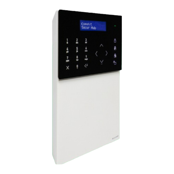
Page 3: Hardware Layout
Hardware layout 1. LCD/CAP-SENSE front panel 7. 2G/3G module connector 2. Microphone 8. Tamper switch 3. Micro USB connector 9. Ethernet RJ45 connector 4. Battery 10. Wired I/O terminal block 5. Battery connector 11. A/C mains terminal block 6. Speaker Control panel installation Removing the bracket... -
Page 4: Lan Module Installation
LAN module installation 2G / 3G Module installation Changing brackets... -
Page 5: Choosing A Proper Mounting Location
Choosing a proper mounting location The following factors should be taken into account when choosing a proper mounting location for the control panel. Functional factors: • A wireless network is established when the control panel is up and running: avoid mounting the control panel close to RF noise sources such as large electrical appliances or air-conditioners. -
Page 6: Installing The Wall-Mounted Brackets
Installing the wall-mounted brackets Installing the desk base... -
Page 8: The Front Panel
The front panel 1. 16x2 character LCD display. 2. LED indicators: green, yellow, red. Enter wizard? 3. Alphanumeric keypad. No:x Ok:↵ 4. Arming / disarming buttons. 5. Back/undo/delete button. 6. Enter/confirm button. 7. Navigation pad / menu button. • Green LED: indicates that the system is armed (steady) or is disarming (flashing). •... -
Page 9: Installer Menu Access
Installer menu access The installer menu contains all the system configuration options. To access the Installer menu: f Enter the installer code, default 001961, using the alphanumeric keypad and press the down arrow. Installation Wizard The installation Wizard is a step-by-step guide that can be used to set up the main features required to get a basic system up and running. -
Page 10: Connect To Wi-Fi
f Enter the APN of the service provider; this will be used to enable data traffic for the SIM card. f Confirm by pressing the Enter/Confirm button. APN: Connect to Wi-Fi? The second step of the installation wizard is connecting to a Wi-Fi network. f Enter the menu by pressing the Enter/Confirm button. -
Page 11: Connect To Lan
Connect to LAN? The third step of the installation wizard is connecting to a LAN network. f Enter the menu by pressing the Enter/Confirm button. Connect to LAN? < ok:↵ > There are two options available for setting the panel IP address •... -
Page 12: Entry/Exit Time
f Use the navigation pad and the alphanumeric keypad to set the correct date. f Confirm by pressing the Enter/Confirm button. Set date: 26:06:2018 Entry/exit time? The fifth step of the installation wizard is used to set the entry and exit delays. The Entry Time is the time lapse available on opening the Entry/Exit zone, allowing you to disarm the system before an alarm is triggered. -
Page 13: Add Rf Zones
Add RF zones? The sixth step of the installation wizard is used to enrol RF detectors. 1. Enter the menu by pressing the Enter/Confirm button. Add RF zones? < ok:↵ > 2. Choose the zone to be enrolled using the navigation keypad and confirm by pressing the Enter/Confirm button. »... -
Page 14: Add Rf Sirens
5. Choose the area to which the zone will be assigned using the navigation keypad and confirm by pressing the Enter/Confirm button. Area: 6. Choose the partition (P1, P2 or P1+P2) to which the zone will be assigned using the navigation keypad and confirm by pressing the Enter/Confirm button. -
Page 15: Add Users
3. Enter the device name using the alphanumeric keypad and confirm by pressing the Enter/Confirm button. Description: Output 01 Add users? The eighth step of the installation wizard is adding users and remotes. f Enter the menu by pressing the Enter/Confirm button. Add users? <... -
Page 16: Add Phonebook
Connect APP? The tenth step of the installation wizard is used to register Comelit App accounts to the control panel. 1. Enter the menu by pressing the Enter/Confirm button. Connect APP? <... -
Page 17: Full Menu
Full menu When this option is enabled the whole menu is visible to the installer. When disabled, only the most important menu items are displayed in the installer menu tree. Deepest parameter configurations are hidden to allow a better browsing of the menus. Service Cloud.Inst. - Page 18 Event type (activation or restore), Event description and Event timestamp are displayed first. f For additional information, press the right arrow on the navigation pad; after doing so all other data will be displayed. f To scroll through the log, use the up and down arrows on the navigation pad. See below for the navigation pattern inside the Event log.
-
Page 19: Mask Tamper
Mask Tamper After enabling this option it is possible to remove the control unit from the bracket and then exit the installer menu without notifying a 24H tamper alarm. It is thus possible to use the control unit from the user menu by “masking” the tamper signal. As soon as the control unit is closed again, the tamper control is reactivated and upon the next reopening the tamper alarm will be notified. -
Page 20: Find Rf Device
Find RF device This menu allows you to launch an individual “Find” command to the registered RF devices by turning on their LEDs to identify them on the premises. After a device has been found, its LEDs will blink for a few seconds and the message “Found!” is displayed. -
Page 21: Forced Settings
This menu allows you to check for and download new firmware releases that may be available in the Cloud. Please bear in mind that the control panel may be set for automatic installation of new releases as soon as they are available on Comelit Cloud. -
Page 22: Timers
Timers Entry Time An entry time is the time available to enter an area via the entry/exit zone and disarm the system. If the entry time is exceeded and no “extra entry time” has been programmed, an alarm is activated. If a zone is assigned to type “Entry/exit 1” it will respect “Entry time 1”... -
Page 23: Siren Timer
Siren Timer Menu dedicated to the options for siren timings. Siren timer Int.siren time Settable parameters are: • Internal siren Timer Time for which the ‘Internal siren’ remains activated. The start of this activation can be postponed with the bell delay. This option is programmed from 0 - 255 minutes for each system. -
Page 24: Time Program
Time program This menu allows you to create and enable time schedules that can be used in different ways according to specific user needs. A time program can be assigned to different entities: a user (to enable temporarily), an output (a light or others) or a programmed arming (to arm and disarm the system at specified times). -
Page 25: Assign Time Program
• Time slot 1 weekly schedule allows you to enter the first week schedule time slot. Weekdays can be selected with the L/R arrow and confirmed / removed with the enter button. T.slot1 week prg M T W T F S S •... -
Page 26: Time Program Composition Example
Time program composition example WEEKLY TIME PROGRAMS TIME SLOTS CALENDAR SCHEDULE AREAS (OPTIONAL)* SCHEDULE 1: 08:30-12:30 Mo Tu We Th Fr Sa 1 total, 2 P1 2: 3:30 PM-7:30 PM Mo Tu We Th Fr Sa 1 total, 2 P1 3: H24-ON 1 total, 2 P1 4: 08:30-7:30 PM... -
Page 28: Profiles & Codes
Profiles & codes This menu allows access to user profile editing and to installer code editing. User Profiles The control panel features some User profiles to allow users to operate on the system with different rights. These permissions are configurable. Accessing a user profile will allow you to check the enabled functions, add functions or remove functions. Profiles &... -
Page 29: Installer 2
Installer 2 • Description: A name for installer 2 can be entered. • New code: A new code (4 to 6 digits) can be entered here or an existing code can be changed. Entering a code that already exists will cause an error message. Installer 2 Code by default is 001961. -
Page 30: Rf Seq.prog
Rf seq.prog To enroll RF detectors you can use the RF Sequential Programming mode. Each Device is automatically acquired in sequence with its own ID. After the control panel has acquired the first detector, the control panel is ready to acquire the next one. If some zone slots are already in use, an alert message will be provided. - Page 31 ZONE TYPE TYPE DESCRIPTION Not Used The programmed input is not used. Will not cause any alarm or zone tamper This type of zone generates an immediate alarm if it is violated while the system is armed. It also causes Alarm the activation of the sirens for the time defined in the respective menu.
- Page 32 ZONE TYPE TYPE DESCRIPTION This zone type will cause a 24 HR alarm if it is activated when the system/area is disarmed and will cause 24 HR an Intruder alarm when the system/area is armed. The panel will also report a ‘24-Hour’ alarm to the Alarm Receiving Centre Normally used for monitoring Panic or hold-up alarms.
- Page 33 • Zone attributes The list of possible zone attributes can be browsed with the Up/Dn arrows. An attribute can be enabled or disabled using the “Enter” button. The letters “Y” or “N” refer to an enabled or disabled attribute. When a zone has no applicable options, the text ‘None’...
-
Page 34: Edit Zones
• Zone Camera This menu item allows you to assign one or more cameras to the zone for video alarm verification. AUX Inputs: moving downwards with the arrow key or trying to move backwards in the menu will cause the display to ask if the user wants to enable AUX input “B”... -
Page 35: Wired Zones
Wired zones Configuration of the two wired zones that are provided on the control panel is carried out via this menu. Devices Wired zones Select zone This menu item allows you to select the zone to be edited. • Description: this menu allows you to edit the zone description. See RF Single zone programming for details on zone descriptions. - Page 36 ◊ Function keys: This menu item allows you to set the F buttons' actions. The keypad has 4 Function buttons and 4 arrow buttons. The F and arrow buttons can assume a different action when pressed. Arrow buttons can be associated with number buttons pressed, for 40 combinations.
- Page 37 ◊ Keypad buzzer setting This menu allows you to set the buzzer function on the keyboard. The user menu provides the same menu as intended for the system. The buzzer is enabled if both system and keypad settings are enabled. - Entry time: Enable the buzzer to sound during entry time - Exit time: Enable the buzzer to sound during exit time - Alarm: Enable the buzzer to sound on alarms...
-
Page 38: Rf Sirens
RF sirens RF output programming follows essentially the same workflow process as zone programming. The output device number must be set at the start. After that, the acquisition procedure can start. Once the output device has been acquired, an output description and output type can be entered. - Page 39 OUTPUT Type Output Operation This output type is used to activate system external sirens and will follow behaviour that is defined External Bell for external bells This output type is used to activate system internal sirens and will follow behaviour that is defined Internal Bell for internal bells Full Arm...
-
Page 40: Edit Devices
Allows you to select which network interface is to be used for the camera (ETH, WiFi, Access Point) • Camera Type: Allows you to select which Comelit camera series is being used. Select “Other” if it is not a Comelit camera. If “Other” is selected, entry of proper RTSP strings is requested. Edit CCTV device •... -
Page 41: Areas
Areas The number of areas that the system is to administrate is set here. Menus include the following: Installer menu Areas Number of areas This is where the number of areas administrated by the system is defined. Keypad numbers can be used to directly enter the number. -
Page 42: Communications
Select zone In this menu it is possible to select the zone for which area logic must be programmed and to toggle between “AND” logic or “OR” logic. AND logic will make the zone activate an alarm only if all its linked areas are armed. OR logic will make the zone activate an alarm even if only one of its linked areas is armed. -
Page 43: Event Report Set
Event report set Communications Event report set • Activation report This menu allows you to set the event activation that will be reported. After this menu has been selected, the first event group is shown at the top of the display (if the FULL MENU option is disabled). At the bottom of the display there are 16 positions that correspond to the 16 receivers. -
Page 44: Messages Recording
Messages recording This menu allows you to customise the event report voice messages that are prerecorded in the control panel memory. The list of existing messages relating to system events can be browsed from this menu. Selecting a message will allow you to listen to, record and delete the message. -
Page 45: Audio Options
◊ ARC TWA: allows you to set the TWA mode for ARC contacts. - SIA AV-01 - CID - Comelit custom protocol (not implemented). • Stop communic. If the "Stop Communicator" menu is Enabled, the Kiss-Off button will stop the call queue, preventing the control panel from performing any other call related to that event. -
Page 46: Event Reporting Opt
Event Reporting opt. • Mains fault del. This menu allows you to enter a time delay before any Mains Fault Event is reported to ARC. Time range: 1 to 255 minutes. Communications Event report opt ◊ Set delay: allows you to enter a delay between 1 and 255 minutes, to be applied before reporting a Mains fault to the ARC. - Page 47 This menu allows you to edit the CID code to be sent to ARC for the selected event. This menu is helpful to customise the CID code according to possible ARC specifications. • SIA mapping ◊ [Event group 1-X] codes - Event grp X: Event 1(-X) code This menu allows you to edit the SIA code to be sent to ARC for the selected event.
-
Page 48: Comm.settings
Comm.Settings This menu allows you to set up all the different communication channels (3G, TCP-IP, Wi-Fi). Communications Comm. settings 3G/2G settings ◊ General settings - SIM number - SIM PIN - Verification nr ◊ Data settings - Data APN - Data Username - Data Password ◊... -
Page 49: System Options
System Options Installer menu System options Arm/Disarm opt. System options Arm/disarm opt. • Forced Arm opt. From here, select the forced alarm option: Bypass, No Forced Arming, bypass and unbypass when closed, bypass and unbypass when exit time expires. ◊ Bypass (DEFAULT): this option behaves as follows: when the user arms the system but there are conditions that prevent them from doing this, the system asks if the user wants to force arming. -
Page 50: Arming Programs
• Fail to set This menu item allows you to enable or disable the fault that comes from zones that are still open at the end of the exit time. A “Fail to set” fault event will be generated if the option is enabled. If the option is not enabled, zones that are still open at the end of the exit time will trigger a burglar alarm. -
Page 51: Supervision Time
Supervision time Supervision time can be set for two main detector families: System options Supervision time • Burglar This menu item allows you to set the supervision time for burglary sensors and devices. Sets the timeout for the supervision fault in case of no valid signal coming from the sensor (supervision signals or activations) Time range: 00.01 hours to 23.59 hours. -
Page 52: Technical Reset
Technical reset This menu allows you to enable the requirement for a technical reset for some the faults and tamper events. If this flag is System options Technical reset enabled, the TECHNICAL RESET command will be available in the “service” installer menu. •... -
Page 53: Hardw. Settings
- Wait HH:MM (wait time in hours and minutes before proceeding with the next action) - Wait MM:SS (wait time in minutes and hours before proceeding with the next action) - Output ON (activate an output) - Output OFF (deactivate an output) Arming and disarming have sub-menus for area selection. -
Page 54: False Code
False code This menu allows you to set how many incorrect codes can be entered on the system before producing a “False code” fault. The possible range is from 1 to 10 times. System options False code Alarm restore This menu allows you to set the logic to be followed in the control panel for restoring alarm events. There are three options: System options Alarm restore •... -
Page 55: Menu Timeout
Menu timeout This menu allows you to set the timeout before the user and installer menu are automatically abandoned due to no operation on the system. System options Menu timeout • Installer menu Setting for the installer menu (1 to 255 min) •... -
Page 56: Walk Test Option
Walk test option This menu allows you to set which zones will be available for the walk test menu within the user menu. The menu also sets which kind of confirmation will be given during the walk test of zones. System options Walk test option •... - Page 58 C E R T I F I E D M A N A G E M E N T S Y S T E M S w w w . c o m e l i t g r o u p . c o m Via Don Arrigoni, 5 - 24020 Rovetta (BG) - Italy...
Need help?
Do you have a question about the Secur HUB and is the answer not in the manual?
Questions and answers