Table of Contents
Advertisement
Quick Links
ATENA EASY
41CPE012EN
METALLIC ADDRESSABLE PANEL
INSTALLATION MANUAL
Attention:
This manual contains information on limitations regarding product use and function and information
on the limitations as to liability of the manufacturer. The entire manual should be carefully read.
The information in this manual is a subject to change without notice!
Advertisement
Table of Contents

Related Manuals for Comelit 41CPE012EN


Summary of Contents for Comelit 41CPE012EN
- Page 1 ATENA EASY 41CPE012EN METALLIC ADDRESSABLE PANEL INSTALLATION MANUAL Attention: This manual contains information on limitations regarding product use and function and information on the limitations as to liability of the manufacturer. The entire manual should be carefully read. The information in this manual is a subject to change without notice!
-
Page 2: Table Of Contents
Atena Easy Addressable Fire Alarm Panel – Installation and Programming Manual Table of Contents 1. INTRODUCTION ................................4 1.1. General Description ............................4 1.2. General Specifications ........................... 4 1.2.1 General Technical Specifications ....................4 1.2.2 Possible Hardware Configurations ....................5 1.2.3 Environment ............................ - Page 3 APPENDIX D ................................... 53 APPENDIX E ................................... 54 DoP No: 002 Comelit Group S.p.A. Via Don Arrigoni 5 - 24020 Rovetta S. Lorenzo BG Italy tel. +39 0346 750 011 - fax +39 0346 71436 email: info@comelit.it - export.department@comelit.it EN 54-2:1997/A1:2006/AC:1999;...
-
Page 4: Introduction
Atena Easy is an addressable fire panel with maximum coverage of 48 zones and up to 2 loops. The panel supports communication protocol Comelit and operation with Comelit addressable device series. Every Loop provides up to 250 devices (detectors and modules, regardless of the type). -
Page 5: Possible Hardware Configurations
Atena Easy Addressable Fire Alarm Panel – Installation and Programming Manual 9 groups for zones’ organization 5 monitored potential outputs: SND1 (Sounder 1) SND2 (Sounder 2) FIRE FAULT (The output is deactivated in case of fault event.) EXT (Extinguishing/ Fire Protection – An output for sending an fire alarm signal to automatic fire extinguishing system) ... - Page 6 Atena Easy Addressable Fire Alarm Panel – Installation and Programming Manual Main power supply In normal operating conditions, the fire panel is powered from the mains voltage line. In case of mains voltage line loss the fire panel is equipped with one rechargeable battery. The characteristics of the main power supply are as follows: ...
-
Page 7: Installation
Atena Easy Addressable Fire Alarm Panel – Installation and Programming Manual 2. INSTALLATION 2.1. Wall Mounting • The panel must be installed in a clean dry place and must not be subjected to impact or vibrations (Figure 1). It must be situated far from heating appliances. -
Page 8: System Components
Atena Easy Addressable Fire Alarm Panel – Installation and Programming Manual • Use the template in the set to fix the mounting holes of the metal box on the wall. • Drill holes (suitable for anchors Ø6mm) on the wall and fix the metal box. •... - Page 9 Atena Easy Addressable Fire Alarm Panel – Installation and Programming Manual PROTECTION CONFIRMED EXTINGUISHING STARTED CONFIRMATION. Lights on permanently in activation of the specialized “In PC” input – see the description on page 12. (yellow) PROTECTION PANEL FAULT EXTINGUISHING SYSTEM FAULT. Lights on permanently in activation of the specialized “In FP”...
-
Page 10: Configuration Of The Basic Modules
Atena Easy Addressable Fire Alarm Panel – Installation and Programming Manual 2.2.2 Configuration of the basic modules Figure 6 – Configuration of the modules in the box: 1 – Main PCB (control panel) 2 – Second loop controller (optional, it may not be present in your system configuration) 3 –... - Page 11 Atena Easy Addressable Fire Alarm Panel – Installation and Programming Manual EXT - Potential, monitored output for fire extinguishing, 24 VDC/ 0.3А. This output is activated in case of a fire alarm condition. FIRE – Potential, monitored output for connection of auxiliary devices (signaling devices for example), 24 VDC/ 0.3А.
-
Page 12: Connection Of Signaling Devices
Atena Easy Addressable Fire Alarm Panel – Installation and Programming Manual 2.3. Connection of Signaling Devices The monitored outputs SND, at activation, provide 24VDC@0,5A to the load connected between them and GND*. The monitored outputs FAULT, EXT and FIRE, provide 24VDC@0,3A to the load connected between them and GND*. -
Page 13: Loop Controller
Receives commands from the main microcontroller and transfers them to the devices connected in the communication line. Up to 250 Comelit devices can be connected to Atena Easy loop controller. The general connection diagram of devices to the loop controller is shown on Figure 13. -
Page 14: Connecting To The Main Power Source
Atena Easy Addressable Fire Alarm Panel – Installation and Programming Manual 2.4. Connecting to the Main Power Source The mains power supply of Atena Easy fire alarm panel is realized with connection of the main power cable to the 230V terminal, mounted in the metal box under the powers source. The connection between the 230V terminal and the main power source is done from the manufacturer. -
Page 15: Connecting A Heat Printer
Atena Easy Addressable Fire Alarm Panel – Installation and Programming Manual 2.6. Connecting a Heat Printer The addressable fire alarm panel Atena Easy is equipped with RS232 interface connector, situated in the middle of the main PCB, for connecting a heat printer. The heat printer allows the technician to print the log file for the alarm and fault events, warnings and changes during programming. -
Page 16: Programming Types
The specialized AtenaProg software is designed for programming of intruder and fire alarm panels produced by Comelit. To program the fire alarm panel Atena Easy you should first to install the AtenaProg software on your computer – the program can be downloaded free of charge on Comelit Website. -
Page 17: Firmware Update From Usb Drive
Atena Easy Addressable Fire Alarm Panel – Installation and Programming Manual Use the Windows Explorer file manager to copy the new image update file (with *.bin extension) in Removable Disk directory. When the copying of the image file completes, remove the Removable Disk, as select Eject option from its dialogue box (right click with the mouse over it). -
Page 18: Programming Of Atena Easy Fire Alarm Panel
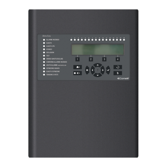
Atena Easy Addressable Fire Alarm Panel – Installation and Programming Manual 5. PROGRAMMING OF ATENA EASY FIRE ALARM PANEL 5.1. General Information for Programming and Operation Addressable fire alarm panel Atena Easy can be programmed directly through the navigation and functional digit buttons on the front panel. - Page 19 Atena Easy Addressable Fire Alarm Panel – Installation and Programming Manual The access codes could be changed only from level Installer - menu 6) General Settings - submenu 6.1) Access codes. There are different restrictions on the panel functions in the relative access levels, which are shown in the following table: Access Level Mode/ Menu...
-
Page 20: Description Of The Operation Modes
Atena Easy Addressable Fire Alarm Panel – Installation and Programming Manual 6. DESCRIPTION OF THE OPERATION MODES In this section you can find detailed descriptions of all operation modes of Atena Easy addressable fire alarm panel. The modes for reviewing of system events are accessible only from level 1 without entering access code. If no alarm, fault or warning messages, active tests and disablements are present, then the panel is in normal operation mode and only the current day and time is displayed. -
Page 21: Review Of Disablements
Atena Easy Addressable Fire Alarm Panel – Installation and Programming Manual 6.3. Review of Disablements The messages for disablements are displayed with normal priority. If no alarm or fault events are present, and there are active disablements in the system, the DISABLED mode is blinking together with the number of the first disablement. -
Page 22: Review Of Warning Messages
Atena Easy Addressable Fire Alarm Panel – Installation and Programming Manual After choosing the button (2) TESTS the screen displays: To exit the review of running tests mode, press CANCEL button. 6.5. Review of Warning Messages The messages for warnings are displayed with low priority. If no alarm or fault events or disablements and tests are present, and there are active warnings in the system, the WARNINGS mode is blinking together with the number of the first message. -
Page 23: Silencing The Internal Buzzer
Atena Easy Addressable Fire Alarm Panel – Installation and Programming Manual 6.6. Silencing the Internal Buzzer The internal buzzer of addressable fire alarm panel Atena Easy is signaling in case of activated alarm or fault events in the system. The buzzer silencing is available from every access level without code entry. To silence the internal buzzer press button. -
Page 24: Description Of The Programming Menus
Atena Easy Addressable Fire Alarm Panel – Installation and Programming Manual 7. DESCRIPTION OF THE PROGRAMMING MENUS The programming menus are accessible from level 2 (Maintenance) and level 3 (Installer) after entering a valid access code. In level 2 could be realized partial programming of parameters, and some values are accessible only for reviewing. In level 3 could be realized full programming and settings, and also to restore the factory default settings, including access codes. -
Page 25: Review Of List Of Events By Date
Atena Easy Addressable Fire Alarm Panel – Installation and Programming Manual 7.1.2 Review of List of Events by Date From the main screen of VIEW LOG menu press (2) FROM button. In “FROM” submenu the installer can extract a list of events by date. -
Page 26: Zones Menu
Atena Easy Addressable Fire Alarm Panel – Installation and Programming Manual 7.2. Zones Menu This menu allows the installer to review and change the status of every zone. In the ‘ZONES’ menus the installer can test and enable/ disable the zones. Up to 48 zone numbers are available for settings. The currently edited zone number is blinking. -
Page 27: Disabling Zones
Atena Easy Addressable Fire Alarm Panel – Installation and Programming Manual 7.2.3 Disabling Zones From the main screen of ZONES menu, select a zone number using the up and down arrow buttons and press button (4) DISABLE. The zone status is changed to DISABLED – the panel stops following the status of the connected devices to the zone and will not alert for alarms and faults from them. -
Page 28: Programming Delays Т2
Atena Easy Addressable Fire Alarm Panel – Installation and Programming Manual Examples for 2 DEVICES action mode operation: EXAMPLE 1 EXAMPLE 2 5 min 5 min Time Time 1 – An incoming alarm signal from Detector 1 and zone reset; 2 –... -
Page 29: Arranging Zones In Groups
Atena Easy Addressable Fire Alarm Panel – Installation and Programming Manual 7.2.8 Arranging Zones in Groups The zones in Atena Easy addressable fire alarm panel can be organized for operation in separate groups. The maximum number of the permissible groups is 9. By default all zones are not associated to a group number – value 0 is set. -
Page 30: Saving The New Found Devices
Atena Easy Addressable Fire Alarm Panel – Installation and Programming Manual 7.3.2 Saving the New Found Devices The loop controller automatically recognizes the types of devices in the loop. In case of finding new devices in the system configuration (Loop 1 or Loop 2) the panel displays the message “ ”, followed by New Loop Devices Found information for the total number of the new devices and the loop number. -
Page 31: Fixing Of Wrong Type Devices
The Atena Easy fire alarm addressable panel operates with full range of addressable detectors, call points, sounders and modules via Comelit communication protocol. According the type of the device, the setting parameters are different. Use the descriptions below to set the devices in your system configuration. - Page 32 Atena Easy Addressable Fire Alarm Panel – Installation and Programming Manual Two special buttons are implemented in the setup menus of the addressable devices: Button ON/ OFF TURN – Using this button the installer can manually to turn on the LED of a device (or the sound for sounders 41SAI000 and 41SAB000) when checking its place of installation or checking for double addresses in the system.
- Page 33 Atena Easy Addressable Fire Alarm Panel – Installation and Programming Manual 41RCS000 – Heat Detector with isolator Use the functional buttons to set the following specialized parameters: – (1) CLASS Press the button to enter the submenu for setting the class for DAY and NIGHT alarm mode.
- Page 34 Atena Easy Addressable Fire Alarm Panel – Installation and Programming Manual 41PAM000 – Manual call point for indoor mounting 41PAE020 – Manual call point for outdoor mounting IP67 Use the functional buttons to set the following specialized parameters: (3) EVENT EVACUATION/ ALARM – Every pressing of the button alternatively changes the type of the event generated with activation of the manual call point: - Event EVACUATION –...
- Page 35 Atena Easy Addressable Fire Alarm Panel – Installation and Programming Manual 41SAB000 – Base with sounder Use the functional buttons to set the following specialized parameters: (1) SND LEVEL – Every pressing of the button alternatively changes the sound level between HIGH/ LOW – as this depends on the number of the connected sounders to the loop: - HIGH –...
- Page 36 Atena Easy Addressable Fire Alarm Panel – Installation and Programming Manual 41IOM010 – Mini input module The 41IOM010 is a compact module with one input. The module monitors and transfers to control panel the state of this input - state ON or state OFF. 41IOM010 is designed for built-in installation in the mounting box of a device. The activation of the 41IOM010 input can be programmed according the application.
- Page 37 Atena Easy Addressable Fire Alarm Panel – Installation and Programming Manual Use buttons to select an activation event. The installer has to choose an activation event using the up and down arrows. Use the left and right arrows to switch over the editable fields.
- Page 38 Atena Easy Addressable Fire Alarm Panel – Installation and Programming Manual 41IOM022 – Module with 2 inputs and 2 outputs The programming is same for all of inputs and outputs. Use the functional buttons to select an input or output number. To program OUT 2 you have to press button MORE >>.
-
Page 39: Addressing Menus
(when operating with Comelit conventional detectors is a must to connect an EOL module at the end of the line). -
Page 40: Set Address
Atena Easy Addressable Fire Alarm Panel – Installation and Programming Manual 7.4.1 Set Address In this submenu the installer can directly set addresses to new devices in the system. The procedure is same with that for self addressing. It is suitable when the installer needs to add single devices to the system configuration at free addresses. -
Page 41: Panel Outputs Menus
Atena Easy Addressable Fire Alarm Panel – Installation and Programming Manual The self-addressing menu shows information about the total number of devices connected to every loop. On the third row the panel shows the first free address for every of the loops. -
Page 42: Sounders Outputs
Atena Easy Addressable Fire Alarm Panel – Installation and Programming Manual 7.5.1 Sounders Outputs In this submenu the installer can disable/ enable the sounders activation and the time delay operation. To access the SOUNDER submenu, enter in the installer’s menu - 5. PANEL OUTPUTS - SOUNDER (1). Attention: In access level 2 you can only review the set delay status (ON, OFF, SCHEDULE), with no rights to change it! The functional buttons have the following action:... -
Page 43: Fault Output
Atena Easy Addressable Fire Alarm Panel – Installation and Programming Manual 7.5.4 Fault Output In this submenu the installer can disable/ enable the fault output activation. To access the FAULT submenu, enter in the installer’s menu - 5. PANEL OUTPUTS – MORE> (4) – FAULT (1). The functional button has the following action: (2) - Press to change the status of the fault output. -
Page 44: Access Codes
Atena Easy Addressable Fire Alarm Panel – Installation and Programming Manual 7.6.1 Access Codes Attention: The access codes can be changed only from access level 3! In this submenu the installer can change the code combinations for access to INSTALLER and MAINTENANCE levels. To access the ACCESS CODES submenu, enter in the installer’s menu - 6. -
Page 45: Setting The Date And Time
Atena Easy Addressable Fire Alarm Panel – Installation and Programming Manual 7.6.2 Setting the Date and Time Attention: The setting of the date and time is available only from access level 3! In this submenu the installer can set the current time and date for the panel. To access the TIME/ DATE submenu, enter in the installer’s menu - 6. -
Page 46: Panel General Settings
Atena Easy Addressable Fire Alarm Panel – Installation and Programming Manual 7.6.4 Panel General Settings In this submenu the installer can make some adjustments for the panel performance. To access the PANEL SETTINGS submenu, enter in the installer’s menu - 6. GENERAL SETTING - 6.4) PANEL SETTINGS. -
Page 47: Company Logo
Atena Easy Addressable Fire Alarm Panel – Installation and Programming Manual The EVACUATION TIMEOUT is a time delay introduced and running until starting evacuation of the site. Enter the submenu and use the up/ down arrow buttons to set the EVACUATION TIMEOUT delay from 0 to 10 minutes. In a fire situation only the sounder of the zone(s) with alarm condition will be activated. -
Page 48: Save Configuration Menu
Atena Easy Addressable Fire Alarm Panel – Installation and Programming Manual 7.7. Save Configuration Menu Attention: Saving the system configuration is available only from access level 3! In this menu the installer performs saving of the new found devices in the system configuration. The panel will ask for confirmation of the action. -
Page 49: Panels Settings
Atena Easy Addressable Fire Alarm Panel – Installation and Programming Manual 7.10.2 Panels Settings To access the PANELS settings, enter in the installer’s menu - 10. NETWORK – 10.2) PANELS. On the screen are listed the panels with their current state in the redundant network: ... - Page 50 Atena Easy Addressable Fire Alarm Panel – Installation and Programming Manual APPENDIX А Table: Event Messages. Message Description Flash Error FLASH Memory error is detected. Ram Error RAM Memory error is detected. New Periphery Devices Found New periphery devices are found in the system configuration. Periphery Device Fault The device is not responding (the device is lost or failed).
- Page 51 Atena Easy Addressable Fire Alarm Panel – Installation and Programming Manual Sounder Disabled The Sounders are disabled. Fire Brigade Output Disabled The fire output is disabled. Fire Protection Output Disabled The extinguishing output is disabled. Fault Output Disabled The fault output is disabled. Zone In Test The zone is in test mode.
- Page 52 Atena Easy Addressable Fire Alarm Panel – Installation and Programming Manual APPENDIX B Table: Text and symbols for introducing device and zone names. In device or zone name entering mode every pressing of up/ down arrow button changes the entered letter or symbol. When moving to the next new position the entering starts from the begging of the table.
- Page 53 Atena Easy Addressable Fire Alarm Panel – Installation and Programming Manual APPENDIX D Two steps of alarming Algorithm.
- Page 54 Atena Easy Addressable Fire Alarm Panel – Installation and Programming Manual APPENDIX E Tree structure of the programming menus. The presented tree structure describes the full access to the programming menus from level 3 – Installer. From access level 2 – Maintenance, some of the programming menus are not displayed or the operation with them is partially limited –...
- Page 55 Atena Easy Addressable Fire Alarm Panel – Installation and Programming Manual Tree structure of the menus – continue.
- Page 56 Comelit Group S.p.A. Via Don Arrigoni 5 - 24020 Rovetta (BG) Italy www.comelitgroup.com...
Need help?
Do you have a question about the 41CPE012EN and is the answer not in the manual?
Questions and answers