Table of Contents
Advertisement
Quick Links
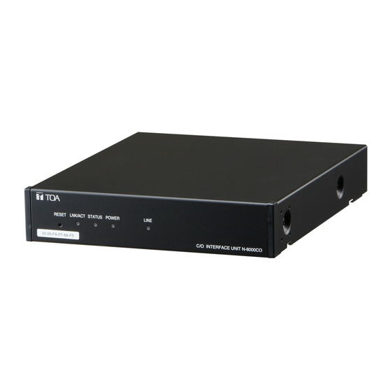
C/O INTERFACE UNIT
TABLE OF CONTENTS
1. SAFETY PRECAUTIONS ............................. 2
2. GENERAL DESCRIPTION ........................... 6
3. FEATURES ................................................... 7
4. NOMENCLATURE AND FUNCTIONS ......... 7
Front .............................................................. 7
Rear ............................................................... 7
5. INSTALLATION ............................................ 8
5.1. Equipment Rack Mounting ...................... 8
5.2. Desk-Top Installation ............................ 10
5.3. Wall Mounting ....................................... 10
Thank you for purchasing TOA's C/O Interface Unit.
Please carefully follow the instructions in this manual to ensure long, trouble-free use of your equipment.
INSTALLATION MANUAL
6. WIRING ....................................................... 12
6.1. Connection Diagram ............................. 12
6.2. Type of Cable ....................................... 14
6.3. Connector Connection ......................... 14
7. ACCESSORIES .......................................... 15
8. OPTIONAL PRODUCTS ............................ 15
N-8000CO
Advertisement
Table of Contents

Subscribe to Our Youtube Channel
Related Manuals for Toa N-8000CO


Summary of Contents for Toa N-8000CO
-
Page 1: Table Of Contents
5.1. Equipment Rack Mounting ...... 8 5.2. Desk-Top Installation ......10 5.3. Wall Mounting ........10 Thank you for purchasing TOA’s C/O Interface Unit. Please carefully follow the instructions in this manual to ensure long, trouble-free use of your equipment. -
Page 2: Safety Precautions
· The supplied rack-mounting screws can be used for the TOA equipment rack only. Do not use them When the Unit is in Use for other racks. • Should the following irregularity be found during... - Page 3 être utilisées pour le bâti de l’équipement fiche du cordon d’alimentation de la prise secteur TOA. Ne pas les utiliser pour d’autres bâtis. et contacter le représentant TOA le plus proche. Pendant l’utilisation de l’appareil Ne pas essayer pas d’utiliser l’appareil dans ces...
- Page 4 7. I f trouble is experienced with this equipment [N8KCOCU], for repair or warranty information, please contact TOA Electronics, Inc.,1350 Bayshore Highway, Suite 270 Burlingame, California 94010, phone (650) 452- 1200. If the trouble is causing harm to the telephone network, the telephone company may request you remove the equipment from the network until the problem is resolved.
- Page 5 12. CAUTION - To reduce the risk of fire, use only No.26 AWG or larger telecommunication line cord. 13. The interconnected telecommunication terminal equipment should be UL Listed and the connections shall be made in accordance with Article 800 of the NEC. Data Equipment: For permissive, programmable and (or) fixed loss loop operation data equipment, in addition to the general requirements for all equipment, information must be provided explaining which jack is associated with each...
-
Page 6: General Description
Caution: Do not defeat the Class I product's earthed connections. 2. GENERAL DESCRIPTION TOA's N-8000CO is C/O interface unit used for the N-8000 Series Packet Intercom System (IP network compatible intercom) employing packet audio technology*. It has an analog central office line circuit, allowing the intercom station to make and receive calls to and from the telephone line. -
Page 7: Features
3. FEATURES • Exchanges, IP stations and various kinds of interface units can be distributed over a data communications network. • Can be connected to an existing local area network (LAN) or wide-area network (WAN). • The dedicated software program enables centralized control with a personal computer. •... -
Page 8: Installation
5. INSTALLATION The N-8000CO can be installed in any of three ways: Equipment rack mounting, Desk-top installation, and Wall mounting. 5.1. Equipment Rack Mounting A) Elevated Operating Ambient - If installed in a closed or multi-unit rack assembly, the operating ambient temperature of the rack environment may be greater than room ambient. - Page 9 Component parts of MB-15B-BK Tapping screw 3 x 14 Composants du MB-15B-BK Vis-taraud 3 x 14 Tapping screw 3 x 8 Vis-taraud 3 x 8 N-8000CO Blank bracket Patte vierge Tapping screw 3 x 8 Vis-taraud 3 x 8 Rack mounting bracket...
-
Page 10: Desk-Top Installation
Machine screw M3 x 6 (supplied with the YC-850) Vis de mécanique M3 x 6 (fournie avec l'unité YC-850) L’unité N-8000CO peut être montée au mur à l’aide d’une patte de montage mural YC-850. Étape 1. Installez l’unité YC-850 sur l’unité N-8000CO. - Page 11 Step 2. Mount the N-8000CO on the wall. Notes • Use appropriate screws for the construction of wall. • Wood screws 3.5 x 20 are supplied with the YC-850. • The socket-outlet shall be installed near the equipment and the plug (disconnecting device) shall be easily accessible.
-
Page 12: Wiring
6. WIRING 6.1. Connection Diagram N-8000CO C/O interface unit Be sure to ground. RJ-45 connector To network To AC mains or a UPS (Uninterruptible power supply system)* Mini-clamp connector Note 232D-02S1B-DA5 (DDK) If there is a danger of lightning strikes,... - Page 13 Use a straight through cable of UTP category 5 or About power supply cord handling more for this connection. The supplied power supply cord is designed for exclusive use with the N-8000CO. Use the supplied power supply cord only with the N-8000CO. 2. C/O line connection...
-
Page 14: Type Of Cable
Outside diameter: ø 1.05 mm or below 6.3. Connector Connection Connect the mini-clamp connector supplied with the N-8000CO, to a cable using a commercially available tool (pliers). Step 1. Cut off two-cable ends in equal length, and insert them Cover (transparent side) securely to a cover section (transparent side) of the mini-clamp connector. -
Page 15: Accessories
Wall mounting bracket: YC-850 Version update information • Download our TOA Products Data, web site (https://www.toa-products.com/international/) to get the up-to-date version for N-8000 software, firmware, and Instruction manuals. • The software version number can be confirmed using the Help menu. - Page 16 Traceability Information for Europe Manufacturer: Authorized representative: TOA Corporation TOA Electronics Europe GmbH 7-2-1, Minatojima-Nakamachi, Chuo-ku, Kobe, Hyogo, Suederstrasse 282, 20537 Hamburg, Japan Germany URL: https://www.toa.jp/ 133-06-00007-01...
Need help?
Do you have a question about the N-8000CO and is the answer not in the manual?
Questions and answers