Table of Contents
Advertisement
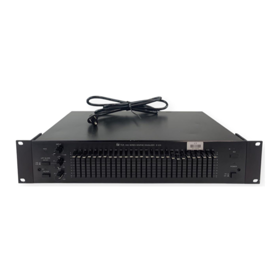
GRAPHIC EQUALIZER
TOA 1000 series
CAUTION
TO REDUCE THE RISK OF ELECTRICAL
SHOCK,
DO
NO USER SERVICEABLE PARTS INSIDE.
REFER
SERVICING
SERVICE PERSONNEL.
Please follow the instructions in this manual to obtain the optimum results from this unit.
We also recommend that you keep this manual handy for future reference.
NOT
REMOVE
COVER.
TO
QUALIFIED
TOA Corporation
Operating Instructions
THE
LIGHTNING
FLASH
ARROWHEAD WITHIN A TRIANGLE IS
INTENDED TO TELL THE USER THAT
PARTS INSIDE THE PRODUCT ARE A
RISK
OF
ELECTRIC
PERSONS.
THE EXCLAMATION POINT WITHIN A
TRIANGLE IS INTENDED TO TELL THE
USER THAT IMPORTANT OPERATING
AND SERVICING INSTRUCTIONS ARE
IN
THE
PAPERS
APPLIANCE.
E-1231
WITH
SHOCK
TO
WITH
THE
Advertisement
Table of Contents

Summary of Contents for Toa 1000 Series
-
Page 1: Operating Instructions
GRAPHIC EQUALIZER TOA 1000 series CAUTION TO REDUCE THE RISK OF ELECTRICAL SHOCK, REMOVE NO USER SERVICEABLE PARTS INSIDE. REFER SERVICING SERVICE PERSONNEL. Please follow the instructions in this manual to obtain the optimum results from this unit. We also recommend that you keep this manual handy for future reference. -
Page 2: Table Of Contents
Contents Cautions General Description Features Front Panel Rear Panel Input/Output Connections Installation Precautions Applications Optional Matching Transformer Mounting Performance Graphs Block Diagram Specifications Accessories Appearance Cautions 1. Do not operate the E-1231 from power mains which exceeds the indicated mains voltage by more than 10%. 2. -
Page 3: General Description
General Description The E-1231 is a single channel, 1/3 octave active graphic equalizer designed to allow clean, accurate audio equalization for stage, studio, or commercial applications. The E-1231 provides 12dB of boost or cut at each of its 28 frequencies, which are centered at ISO 1/3 octave increments from 31.5Hz to 16kHz. -
Page 4: Front Panel
Front Panel Lowpass Filter Slope Selection Switch This switch sets the lowpass filter's per octave attenuation for either 6dB or 12dB. Peak Indicator LED The peak indicator LED lights when either the input or the output level reaches 3 dB below clipping. Input Level Control This control adjusts the input gain by ±12dB to allow the use of a wide range of input sources. -
Page 5: Rear Panel
Rear Panel AC Fuse Holder When replacing, be sure to use the fuse of specified rating and type to avoid the possibility of fire. Fuse rating 220-240V version 250V T80mA 120V version 250V 0.2A AC Power Cord Ground Screw Terminal Hum can result from a ground loop to be formed when the E-1231 is connected to other equipment. -
Page 6: Input/Output Connections
Input/Output Connections E-1231 E-1231 Installation Precautions Ground Loops In any audio system, there are numerous ways by which ground loops can be created. For example, they may occur when the E-1231 is mounted in a rack cabinet, or through AC ground when the E-1231 connected with preamps, mixers, etc. These ground loops may cause hum and noise if care is not taken during connection. -
Page 7: Applications 7
Applications Feedback Prevention When the overall gain of a sound system is increased, feedback will occur at frequencies where the system response has peaks. Suppose the system has an uneven frequency response like that shown in the following diagram. The frequency at which feedback will occur when gain is increased is about 500Hz. - Page 8 Applications Equalization for music The Graphic Equalizer is designed not only for use in preventing feedback and equalizing uneven room frequency response to be flat, but also for equalizing frequency response to your tastes and producing favorable sound for you. Fig.1 shows each frequency band and its corresponding auditory feeling.
-
Page 9: Optional Matching Transformer Mounting
Optional Matching Transformer Mounting [CAUTION] THESE SERVICING INSTRUCTIONS ARE FOR USE BY QUALIFIED PERSONNEL ONLY. TO AVOID ELECTRIC SHOCK DO NOT PERFORM ANY SERVICING OTHER THAN THAT CONTAINED QUALIFIED TO DO SO. REFER ALL SERVICING TO QUALIFIED SERVICE PERSONNEL. The E-1231's input and output are electronically balanced. These can be converted to transformer balanced input and output using the optional matching transformer LT-101 (input) and LT-102 (output). -
Page 10: Performance Graphs
Performance Graphs Frequency Response (Each slider is set at a max or min position) Frequency Response (ex. 630Hz, 800Hz, 1kHz slider) Low pass Filter Frequency Response (ex. 800Hz slider) High pass Filter — 10 —... -
Page 11: Block Diagram
Block Diagram — 11 —... -
Page 12: Specifications
Specifications Frequency Response ±1dB, 20Hz to 20kHz Total Harmonic Distortion Less than 0.01% at 1 kHz, all sliders at 0 position, rated output Equalization Center Frequencies 31.5Hz to 16kHz 31.5Hz, 40Hz, 50Hz, 63Hz, 80Hz, 100Hz, 125Hz, 160Hz, 200Hz, 250Hz, 315Hz, 400Hz, 500Hz, 630Hz, 4kHz, 5kHz, 6.3kHz, 8kHz, 10kHz, 12.5kHz, 16kHz Rated Input Level + 4dB (INPUT LEVEL CONTROL set for 0 position)


Need help?
Do you have a question about the 1000 Series and is the answer not in the manual?
Questions and answers