Advertisement
Quick Links
Advertisement

Related Manuals for Karma Leon F Kameleon


Summary of Contents for Karma Leon F Kameleon
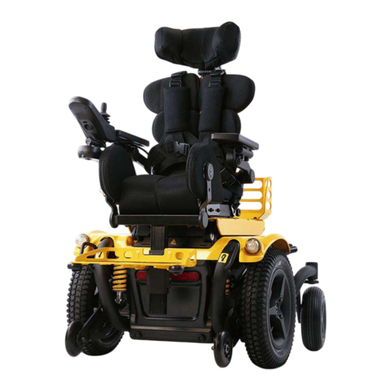
- Page 1 User manual Leon F Kameleon...
- Page 3 1. index 1. index ______________________________________________________ 0 2. How to contact Karma ________________________________________ 1 3. Declaration of conformity ______________________________________ 2 4. Introduction _________________________________________________ 3 4.1 Chassis number ________________________________________ 3 5. Used symbols for warning, caution and note _______________________ 5 6. Warranty ___________________________________________________ 6 7.
- Page 4 10.4.6 Upholstered armrest _______________________________ 21 10.4.7 Legrest _________________________________________ 22 10.4.8 Powered legrest adjustment (Optional) _________________ 23 10.4.9 Upholstered headrest (Optional) ______________________ 24 10.4.10 Upholstered hip supports (Optional) __________________ 25 10.4.11 Knee support panels (Optional) _____________________ 25 10.4.12 Upholstered lateral supports (Optional) _______________ 25 10.4.12 Positioning belt __________________________________ 26 10.5 The controls _________________________________________ 27 10.5.1 Side steering control _______________________________ 27...
- Page 5 12.3 Display _____________________________________________ 47 12.3.1 Battery indicator (top bar) ___________________________ 47 12.3.2 Focus light (top bar) _______________________________ 48 12.3.3 Profile name (main screen) __________________________ 48 12.3.4 Clock (main screen) _______________________________ 48 12.3.5 Speed display (main screen) ________________________ 49 12.3.6 Speed bar (main screen) ___________________________ 49 12.3.7 Inhibit (main screen) _______________________________ 49 12.3.8 Set functions (main screen) _________________________ 50 12.3.9 Additional options (main screen) ______________________ 50...
- Page 6 12.6 R-net Connectors _____________________________________ 58 12.7 Joystick _____________________________________________ 59 13 Electric system _____________________________________________ 60 13.1 Batteries ____________________________________________ 60 13.2 Main fuse ____________________________________________ 61 14 Using the wheelchair ________________________________________ 62 14.1 General warnings and advices ___________________________ 62 14.2 Use in combination with other products ____________________ 63 14.3 Hot and cold surfaces __________________________________ 64 14.4 Danger of pinching ____________________________________ 64 14.5 Surroundings _________________________________________ 65...
- Page 7 19 Transport of the wheelchair ___________________________________ 81 19.1 Transportation using Dahl Docking station __________________ 81 19.1.1. Mounting of the Dahl locking adapter on the wheelchair ___ 82 19.1.2. Locking procedure ________________________________ 88 19.1.3 Unlocking procedure _______________________________ 89 19.1.4 Manually unlocking in case of electric failure or accident ___ 89 19.1.5 Safety belt _______________________________________ 90 19.2 Backrest, legrest and headrest settings during transportation ___ 94 19.3 Transportation on an airplane ___________________________ 102...
- Page 8 23.1 Diagnostics R-Net LCD ________________________________ 116 24 Technical specifications _____________________________________ 117 25 accessories ______________________________________________ 122...
- Page 9 Chia-Yi 621 Taiwan www.karma.com.tw European representative: Karma Mobility S.L. C/ Periodista Francisco Carantoña Dubert, 23 Bajo 33209 Gijón - Asturias (Spain) phone: +34 984 390 907 karma@karmamobility.es Produced and published by Karma Medical, Taiwan Technical changes and print errors prohibited.
- Page 10 3. Declaration of conformity Leon F Kameleon Series...
- Page 11 Karma runs the policy of continuously product improvement. Therefore, pictures of products or options as shown in this manual might be different from what you see in the product. Karma reserves the right to make changes to the product without prior notice.
- Page 12 The used symbols on the chassis plate are explained below: describes the model and type of the product. stands for indoor- and outdoor use (Class B). stands for the date of production. this icon stands for the maximum driving speed. this icon stands for the maximum slope to drive on.
- Page 13 5. Used symbols for warning, caution and note General warnings are indicated by using a symbol. There are three levels of warnings: 1. Warning If you see this sign, please use extreme caution where this symbol appears. Neglecting these warnings can lead to personal or material damage.
- Page 14 6. Warranty Karma Medical supplies a warranty of frame for a period of 5 years and electrical system (controller, motor, charger, actuator and PCB) for a period of 1 year after delivery to the customer. Your local supplier will carry out this warranty.
- Page 15 “cleaning”. 9. Tyre pressure The Leon F Kameleon uses air-filled front tyres and solid or air-filled tyres in the rear. The choice of having solid or air-filled rear tyres is made by the user during the ordering of the wheelchair. In order to prevent tyre damage and to preserve the performance of the wheelchair, the tyre pressure must be checked at least on a monthly basis.
- Page 16 10. Wheelchair 10.1. Chassis The chassis is the base of the wheelchair. It contains wheels, drive motors, batteries and electronics. The steel parts of the chassis are electrolytic anodized and powder coated to ensure a long life without corrosion. Each of the front wheels is propelled by a powerful drive motor. These motors also take care for the steering of the wheelchair.
- Page 17 10.1.2 Anti-tippers The anti-tippers prevent the wheelchair tipping over at all time. The anti- tippers are standard equipped and positioned at the front of the chassis. DO NOT operate the wheelchair without anti-tippers being installed, otherwise the wheelchair might tip over and hurt the user. 10.1.3 Lights and reflectors (Optional) The chassis has very strong and bright LED lights to make sure you can have a safe drive in the dark.
- Page 18 10.1.4 Battery compartments The batteries are mounted as low as possible in the center into the chassis, to provide an optimal center point of gravity. This results in a maximum stability of the wheelchair. The compartment can hold maintenance-free batteries up to 80Ah.
- Page 19 Before removing the batteries, first remove the main fuse. It helps to reduce the risk of short circuit or electrical shock. See the paragraph “main fuse”. Before reconnecting the battery, read the wiring instructions on the inside of the battery cover. 10.1.5 Main fuse The chassis contains a main fuse which is located at the rear of the chassis.
- Page 20 to eliminate the cause first. And then, press down the circuit breaker. You will be able to drive again. If the main fuse has blown, do not replace the fuse immediately. First contact your local supplier to have the wheelchair checked. Only use original main fuses as replacement.
- Page 21 10.2 Seat lift (Optional) The seat lift is centrally mounted into the chassis. With this lift the seat can be raised stepless up to 300mm. This enables the user to have more freedom of movement, not only in horizontal area, but also in the vertical area. The seat lift can be stopped at any height and will be automatically locked in position.
- Page 22 10.3 Quick release seat mounting With the quick release seat mounting system, the seat can be taken off the chassis easily and fast. The quick release rails can be adjusted forward or backward on the seat base panel to achieve a right center of gravity positioning of the seat on the chassis.
- Page 23 10.4 Seat The seating system is designed to optimize the seating comfort to the user. It can be adjusted in seat depth and seat width. The best possible sitting support is accomplished by an individual combination of a wheelchair base and proper seating elements.
- Page 24 10.4.1 Seat pan with cushions The seat pan is a sheet metal frame which is adjustable in depth, width and shape. Seat pan short Seat pan one side extended in depth The seat depth can be adjusted left and right side independently in steps of 20mm.
- Page 25 When the seat is set at the widest setting, the gap between both left and right set pan will be filled by the T-panel shown below. Seat pan T-panel 10.4.2 Seat curve foam wedge (Optional) The seat can be shaped by adding a hard foam wedge. This wedge has an ergonomic S-shape which gives more contours to the seat.
- Page 26 10.4.3 Seat tilt (Optional) The seat tilt can be used to release pressure and improve stability. The tilting angle is from 0 to 45°. The tilt can also be used when driving down a slope for compensating the negative seat angle. This provides a more stable seat position and safe driving.
- Page 27 10.4.4 Upholstered backrest The upholstered backrest is set up by different backrest modules which can be set and adjusted to the user’s requirements and needs. These modules can be combined in any kind of ways. The main frame of the backrest (backbone) can be extended in height, which is in order to “grow”...
- Page 28 10.4.5 Power recline backrest (Optional) The power recline backrest can be set from 85° to 135°. It gives the user the possibility to move into a relaxing position or a very active, upright sitting position. Max 135° Upright backrest Reclined backrest The backrest has a build-in (optional) shear reduction to keep the backrest in the same position toward the upper body when reclining.
- Page 29 10.4.6 Upholstered armrest The PU upholstered armrests provide solid and comfortable support of the arm which result in a stabile seating position. The armrest has a soft PU upholstery on the top side which is easy to clean. Each armrest has an adapter tube for a joystick or table mount (T).
- Page 30 10.4.7 Legrest The legrest is adjustable in height, knee angle, footplate angle and the footplate can be flipped up. The footplate has slots (S) and thread holes to mount foot straps. The front edges of the footplate are secured with small bumper wheels to avoid damage to the footplate or walls in case of a collision.
- Page 31 10.4.8 Powered legrest adjustment (Optional) With a powered legrest the knee angle can be set from 90° up to a nearly fully stretched leg angle. The biomechanical movement (turning point at knee height) ensures the lower leg length will always remain the same. Legrest at 90 degrees Legrest stretched When stretching the legrest, it always checks if there is no obstructions...
- Page 32 10.4.9 Upholstered headrest (Optional) The multi adjustable headrest is adjustable in height, depth, angle and shape to meet the requirements of the user. It can be taken off without losing its settings. As an additional option, a rail can be mounted between the backrest and headrest adapter to move the headrest out of center.
- Page 33 10.4.10 Upholstered hip supports (Optional) The upholstered hip supports offer side support to your hips or upper legs. The support is adjustable in height, depth, width and angle. The PU pads offer stable and comfortable support. Upholstered hip supports 10.4.11 Knee support panels (Optional) The PU knee support panels (K) can be added to give more side supports in the front area of the seat cushion.
- Page 34 10.4.12 Positioning belt For positioning, several types of positioning belts are available. Fixed seat position belt Automatic retraction position belt Positioning belts shall not be used as a car safety belt. If transported in a car, the user needs to wear, besides the positioning belt, an additional car safety belt.
- Page 35 10.5 The controls 10.5.1 Side steering control Side steering control Side steering, swing away The product has a side steering control unit, which is either mounted on the left or right armrest. The joystick module can be mounted on a fixed bracket or on an (optional) swing away mechanism.
- Page 36 11. First setup Before using, the wheelchair needs to be adjusted and set up for the user. In this chapter, we will explain all the setup which needs to be done before the first drive. Before using the wheelchair, it is vital to make the right setup for the user. A non-proper setup of the wheelchair might lead to uncontrolled driving which can result in personal or material damage.
- Page 37 The stiffness of the suspension can also depend on the user’s weight. The settings need to be done by setting and testing. We advise you to start with a stiffer setting, since this results in the best driving control. If the suspension is too hard, you can set it softer by turning the ring more counterclockwise.
- Page 38 11.2 Seat adjustments Before using the wheelchair, the seat must be set to the right size for the user. Mostly this will be done by your local supplier, together with your therapist. A well-adjusted seat will give you optimum support and comfort. 11.2.1 Seat width To increase the seat width, the seat frame can be slide in and out to the required width in steps of 12.5 mm on each side.
- Page 39 step 6: while the right seat width is set, tighten the four bolts again in the designated holes. Put back the top seat plate, re-tighten all the screws and finish the setting. 11.2.2 Seat depth The seat depth is arranged by two seat panels overlapping each other. By changing the amount of overlapping, we can change the seat depth.
- Page 40 11.2.3 Adding the T-shaped panel If the seat width is set to its widest size, a gap will appear between the two top seat plates. For this issue we can use so-called T-shaped panel. This panel can be ordered separately as an option. Seat with T-shaped panel in the front T-shaped panel mounted The T-shaped panel can be ordered independently as an option if the...
- Page 41 11.2.4 Seat spread adjustment The seat can be spread out up to 15 degree on each side individually and must be set to the right size for the user. Mostly this will be done by your local supplier, together with your therapist. A well-adjusted seat will give you optimum support and comfort.
- Page 42 11.2.5 Knee support settings The optional knee supports can be mounted on the front of the seat on each side. Knee supports mounted outside Knee supports mounted in- and outside Mounting of the knee supports on the inside and outside To mount the outside knee supports, simply use the two bolts (I) and position the panel flat on the side of the seat plates into one of the mounting holes.
- Page 43 11.2.6 Hip supports settings The hip support brackets can be mounted on the designated holes on the side of the seat plates. step 1: use the two bolts (L) to mount the hip support. Mounting of hip support Adjusting of hip support step 2: To adjust the height, depth, width and angle, loosen the four bolts (M) slightly, then the support can be moved.
- Page 44 11.2.7 Backrest settings Setting the backbone height of backrest: To adjust the backbone height, we need to remove the backrest covers (C). step 1: to remove the backrest covers, loosen the bolts of both sides (D). step 2: to change the height, loosen the range of hand nuts (H) slightly. step 3: now you can pull up the yellow front backbone panel (G) to the required height.
- Page 45 Setting the backrest width and height: To set the width and height of the backrest panels, we need to take the following steps: step 1: loosen the hand nuts of each backrest panel individually. As you notice, the frame has vertical slots in the rear and horizontal slots in the front.
- Page 46 11.2.8 Lateral supports settings The lateral support brackets can be mounted on the holes on the rear of the backrest panels. step 1: use the two bolts (L) to mount the lateral support. step 2: To adjust the depth and width, loosen the two bolts (M) slightly, then the support can be moved.
- Page 47 11.2.9 Legrest settings Setting legrest length: To adjust the legrest length, please take the following steps: step 1: loosen the four bolts (L) whilst holding the legrest with one hand. step 2: now move the legrest into the desired height and tighten all the bolts. step 3: to set the legrest into an extreme short setting, we can disassemble the footplate bracket (Q) and turn it 180 degrees to mount it back again Setting legrest angle:...
- Page 48 Setting footplate angle: The footplate angle can be adjusted by rotating the two adjustment bolts (A) on the footplate bracket. step 1: to reduce the angle between legrest tube and footplate, turn the both adjustment screws into the clockwise direction. step 2: to increase the angle, turn the both adjustment screws into counterclockwise direction.
- Page 49 11.2.10 Armrest settings Setting armrest height: To adjust the armrest height, please take the following steps: step 1: loosen up the bolts (A) slightly until the armrest can be moved. By loosening both rotation points of the armrest, it is possible to move the armrest up and down into the required height.
- Page 50 Setting armrest angle: step 1: loosen up the bolt (D). step 2: move the armpad into the required angle. step 3: tighten the bolt (D) to secure the armrest angle setting. Setting armrest depth: step 1: loosen up the four bolts (E). step 2: slide the armrest pad into the requested position.
- Page 51 11.2.11 Headrest settings Headrest height, depth and angle settings: step 1: remove the rubber covers (E) on the three headrest joints. step 2: loosen the three bolts (F) until you can move the headrest. step 3: move the headrest into the required position. step 4: tighten all the bolts firmly to secure the headrest position.
- Page 52 Headrest rotation point settings: If the headrest has a ball joint option, you can change the angle of the headrest pad: step 1: loosen the bolt (G) slightly until you feel you can move the joint. step 2: move the headrest pad into the required position. step 3: tighten the bolt (G) to secure the headrest position.
- Page 53 11.2.12 Positioning belt The positioning belt can be optionally adjusted in length and anchoring point. To change the secure position, simply follow the next steps: step 1: loosen the screw (T) using an 4mm Allan key. step2: move the bracket in the required position. step3: retighten the screw again.
- Page 54 12 Control panel The wheelchair uses a color screen joystick module. With this joystick module all functions of the wheelchair can be controlled. This joystick module can be mounted on the left or right armrest or even as an integrated desktop control unit.
- Page 55 12.3 Display The color LCD screen is split into 3 areas of information. The Top Bar, the Base Bar and the Main Screen Area. 12.3.1 Battery indicator (top bar) This displays the charge available in the battery and can be used to alert the user to the status of the battery.
- Page 56 12.3.2 Focus light (top bar) When the wheelchair system contains more than one method of direct control, such as a secondary Joystick Module or a Dual Attendant Module, then the Module that has control of the wheelchair will display the In-Focus symbol. 12.3.3 Profile name (main screen) The profile name shows in which drive profile you are now.
- Page 57 12.3.5 Speed display (main screen) This gives a proportional display of the wheelchairs speed. The Arc begins at 0% and has a programmable maximum. The programmable parameter is Max Displayed Speed. The speeds can be set in mph or km/h. The standard setting km/h.
- Page 58 12.3.8 Set functions (main screen) Displays the sections of the chair currently selected for movement, the name given to the selection and a direction arrow showing what sort of movement is available. Besides the screen you use for driving or controlling the seat functions, there are also other screens which show information.
- Page 59 12.3.10.1 Restart message This icon is show when the system to be restarted. (Most of the time when a module has been exchanged or added.) 12.3.10.2 Timer message This symbol is displayed when the control system is changing between different states. An example would be entering into Programming Mode.
- Page 60 For more explanation about the trip code we refer to the chapter: trouble shooting. 12.3.11 Current profile (base bar) The currently selected Profile is shown in numeric form. 12.3.12 Motor temperature (base bar) This symbol is displayed when the control system has intentionally reduced the power to the motors, to protect them against heat damage.
- Page 61 Keypad locking To lock the wheelchair by using the keypad lock: - While the wheelchair is switched on, depress and hold the ON/OFF button. - After 1 second the control system will beep. - Now release the ON/OFF button. - Deflect the joystick forwards until the control system beeps. - Deflect the joystick in reverse until the control system beeps.
- Page 62 Locking the wheelchair by using a physical key Locking key To lock the wheelchair with the key lock: - Insert and remove the supplied PGDT key into the charger socket. - The wheelchair is now locked. To unlock the wheelchair: - Insert and remove the supplied PGDT key into the charger socket.
- Page 63 12.4 Buttons The joystick module has several buttons which will be explained below. 12.4.1 On/Off button The On/Off button applies power to the control system electronics, which in turn supply power to the wheelchair’s motors. Do not use the On/Off button to stop the wheelchair unless there is an emergency.
- Page 64 12.4.4 Speed increase button This button increases the speed setting. (It does not increase the maximum speed!). 12.4.5 Mode button The Mode button allows the user to navigate through the available operating modes for the control system. The available modes are dependent on programming and the range of auxiliary output devices connected to the control system.
- Page 65 12.4.10 Right Indicator Button and LED This button activates and de-activates the wheelchair’s right indicator. Depress the button to turn the indicator on and depress the button again to turn it off. When activated the right indicator LED will flash in sync with the wheelchair’s indicator(s).
- Page 66 12.6 R-net Connectors To connect the Communication Cables: • Holding the connector housing, firmly push the connector into its mate until you can no longer see the yellow plastic. The connectors are secured using a friction system. To disconnect the Communication Cables: •...
- Page 67 12.7 Joystick The joystick is primarily used to drive the wheelchair. Just push the joystick into the direction you want to drive, and the wheelchair will start to move in that direction. The secondary purpose of the joystick is to navigate through men menu of the wheelchair.
- Page 68 13 Electric system 13.1 Batteries The wheelchair has two serial-connected 12-volt maintenance free batteries for the power supply. The capacity of the batteries can be up to up to 80Ah. (Battery box sizes L: 260 x W: 168 x H: 210 mm). The batteries are fitted in the middle of the chassis to arrange a low center point of gravity.
- Page 69 If the fuse is blown, please contact your local authorized supplier. He should check the wheelchair first before replacing the main fuse. The fuse only blows if a serious problem occurs. Only use original spare part fuses of Karma. Using other fuses might damage the electronic system or even cause fire.
- Page 70 14 Using the wheelchair 14.1 General warnings and advices Please read this section of the manual very carefully as it contains issues related to safety and possible hazards.
- Page 71 ● A warning not to operate the wheelchair with depleted batteries, since the occupant could be stranded. 14.2 Use in combination with other products Different- or customized seat: Changes which are made by third parties are not covered by the warranty and responsibility of Karma Medical.
- Page 72 14.3 Hot and cold surfaces Some parts of the wheelchair can reach high temperatures when exposed to direct sun. Please be careful with touching especially the plastic parts under these circumstances in order to prevent skin burning. The wheelchair can reach low temperatures when exposed to cold weather (below zero degrees Celsius).
- Page 73 All areas where there might be a risk of pinching are indicated by these warning decal: 14.5 Surroundings Special care has been taken to make sure that the change that the surroundings pinches him or herself is minimal. However, there are few situations that might lead to injury.
- Page 74 Check the tires at the same time for wear and damage. Replace if necessary. ● In order to ensure that your wheelchair is in good condition, please contact Karma authorized dealers regularly and make further wheelchair inspection and maintenance records. We recommend that you inspect and maintain your wheelchair every six months.
- Page 75 14.7 Use on slopes: driving on downhill slopes Driving on downhill slopes must always be done at a low speed and with great care. Avoid sudden braking, abrupt avoidance maneuvers and never maintain a speed higher than that at which you can maneuver the wheelchair in a safe and secure manner.
- Page 76 The position of the seat in height and angle or the position of the backrest has great influence on the stability of the wheelchair when driving on slopes. Make sure the seat is in the optimal driving position to avoid tipping over.
- Page 77 The position of the seat in height and angle or the position of the backrest has great influence on the stability of the wheelchair if driving on slopes. Make sure the seat is in the optimal driving position to avoid tipping over. 14.9 Driving on sideways slopes Driving on a sideways slope must always be performed with great care.
- Page 78 The position of the seat in height or the position of the backrest has great influence on the stability of the wheelchair if driving on slopes. Make sure the seat is in the optimal driving position to avoid tipping over. 14.10 Obstacle climbing Do not drive the wheelchair over obstacles of a height bigger than 50mm.
- Page 79 14.11 Use in presence of electromagnetic fields Use your cell phone only when the wheelchair is switched off. Although the wheelchair is tested and approved for electromagnetic interference, there is a very small change that strong electromagnetic fields from cell phones or some other electrical products lead to unexpected and unpredictable electrical reactions from the wheelchair.
- Page 80 15 Driving the wheelchair The wheelchair is designed for indoor and outdoor use. When driving indoors, you must be careful when driving in, for example, narrow passageways, when passing through doors and entryways as well as when using elevators, ramps, etc.
- Page 81 4. Carefully move the joystick forward to drive forward, and backward to drive backward. 5. The speed of the wheelchair is adjusted continuously by the joystick being moved different distances forward and backward respectively. The wheelchair's electronics make creep driving possible over curbs (max. 50mm.). You can drive up to the curb, and then carefully drive over it.
- Page 82 15.3 Stopping the wheelchair If you would like to stop simply move the joystick slowly towards the center and release the joystick. The wheelchair will come to a gentle stop. If you want to stop more quickly, simply let go of the joystick. It will put itself back into neutral position, which makes the wheelchair stop.
- Page 83 Screen example of the seat function menu By moving the joystick to the left or right you can switch between different powered seat function. One the required seat function is shown on the display, move the joystick forward or backward to activate the seat function in one direction.
- Page 84 17 Handling the mechanical brakes The drive motors of the wheelchair have electromechanical brakes. The brake can be released to set the wheelchair into freewheel mode. In freewheel mode the wheelchair can be pushed. This might be necessary to move the wheelchair in certain cases.
- Page 85 18 Charging the maintenance free batteries The amount of charge in your maintenance free batteries is depending on a number of factors, including the way you use your wheelchair, the temperature of the maintenance free batteries, their age and the type of maintenance free batteries used.
- Page 86 If only two red LED's are flashing, it indicates that the maintenance free batteries are empty and should be charged immediately. If the battery indicator shows only two segments in flashing, you should charge the batteries as soon as possible. This flashing is a warning signal. You are still able to drive the wheelchair but only for a short distance.
- Page 87 18.2 Charging socket The charger socket can be found on the front side of the joystick module. If the wheelchair has an integrated desktop control, the charger socket will be on the side of the joystick module. Charger socket position Charger The wheelchair can be delivered with a battery charger.
- Page 88 Be sure that the charger plug is pushed fully in position. You will not be able to drive the wheelchair when the charger is connected. If the wheelchair does drive with the charger plugged in, contact your local authorized supplier. In some occasions it might be the case that your local supplier will deliver the wheelchair with a different brand charger.
- Page 89 19 Transport of the wheelchair 19.1 Transportation using Dahl Docking station Leon F Kameleon has also been crash tested using a Dahl docking station tie down system according to ISO 7176-19:2008, where the wheelchair is facing forward in driving direction (driving direction like the driver seat)
- Page 90 For detailed information about the Dahl Docking system, please visit the homepage: www.dahlengineering.dk To fit the Dahl docking plate, Karma has created a special kit for Leon F/ Leon chassis which included the base mounting plate and two mounting bolts. This kit is available under Karma part no: 191700000061...
- Page 91 The Dahl Docking station is only allowed to build into a vehicle by trained and authorized staff of a registered car adaptation company. For ordering the Dahl Docking and its accessories, please contact Dahl Engineering in Denmark for further details. You can find Dahl at www.dahlengineering.dk To mount the Dahl locking plate on the Leon F chassis, take the following steps: Step 1: remove the front cover bolts and lift the cover off by first tilting it.
- Page 92 Step 3: pull out the batterey box and disconnect main battery cable. Step 4: place the mounting plate inside the chassis on the bottom Step 5: tighten the two bolts into the mounting holes to fix the mounting plate.
- Page 93 Step 6: mount the Dahl locking plate by using the 5 high grade Dahl bolts on to the chassis. Secure them with Loctite 222 and tighten them, but not too tight. (20-24Nm). The special Dahl high grade Torx bolts (Dahl part no: 502800) only come in one length which is often too long.
- Page 94 Dahl Docking set The Dahl Docking station is only allowed to build into a vehicle by trained and authorized staff of a registered car adaptation company. For ordering the Dahl Docking and its accessories, please contact Dahl Engineering in Denmark for further details. You can find Dahl at www.dahlengineering.dk Dahl docking station...
- Page 95 Dahl docking station mounted on the floor Docking station and docking plate on chassis...
- Page 96 19.1.2. Locking procedure Drive the wheelchair slowly into the vehicle and make sure you center your wheelchair in the middle of the docking module. If being well positioned the locking system will also guide the wheelchair into the docking station. Keep in slowly driving until you feel the wheelchair is hitting the end position in the docking station.
- Page 97 19.1.3 Unlocking procedure To unlock the wheelchair, first open up the car safety belt. Then switch on the wheelchair and switch to drive mode. Now push the release button of the Dahl Docking station. You will hear a firm click. The locking bolt is now retracted, and the wheelchair can drive in reverse direction out of the Docking station.
- Page 98 19.1.5 Safety belt If the user is transported in his wheelchair, it is necessary to use a car safety belt to secure the wheelchair user. Positioning of the car safety belts for wheelchair users The wheelchair has been crash tested using a Dahl 3-point occupant safety belt, model 500984.
- Page 99 Optimal angles for a safety belt used by the wheelchair user The shoulder part (1) of the safety belt should be positioned according to the figure below. Shoulder safety belt positioning...
- Page 100 Picture of improper belt fit Picture of proper belt fit...
- Page 102 19.2 4-point tie down restraint system The wheelchair must only be transported in a vehicle that is approved or adapted for such purposes. It is safest if the wheelchair is separated from the driver’s compartment. Transportation in a trailer is also an optional recommendation.
- Page 103 The position belt of a wheelchair is not meant to be used as a car safety belt. It only prevents the user from sliding out of the seat while driving the wheelchair. If a user is transported in his wheelchair, he or she should wear an extra car safety belt, which is attached to the vehicle like all the car safety belts.
- Page 104 19.2.1 Transportation guideline The wheelchair has a 4-point heavy duty webbing restraint. Using two brackets on the front end and two brackets on each rear side of the chassis. The brackets are indicated with a sticker. These securing points and its location have been designed and successfully tested according to ISO7176-19:2008 The angle of the straps should be around 45°...
- Page 105 Alterations or substitutions should not be made to the wheelchair securement points or to structural- and frame parts or components without consulting the wheelchair manufacturer. 19.2.2 Safety belt If the user is transported in his wheelchair, it is necessary to use a car safety belt to secure the wheelchair user.
- Page 106 optimal angles for a safety belt used by the wheelchair user The shoulder part (1) of the safety belt should be positioned according to the figure below. shoulder safety belt positioning...
- Page 108 picture of improper belt fit picture of proper belt fit...
- Page 109 - Alterations or substitutions should not be made to the wheelchair securement points or to structural and frame parts or components without consulting the manufacturer. - Only use "gelled electrolyte" batteries on powered wheelchairs when used in a car. 19.3 Backrest, legrest and headrest settings during transportation During transportation in an occupied position, the backrest of the wheelchair needs to be set into an upright position.
- Page 110 19.4 Transportation on an airplane When transporting your wheelchair by air, you should primarily pay attention to the following in below: 19.4.1. Batteries Gel batteries: In most cases, they do not need to be removed from the wheelchair. The batteries only need to be disconnected from the wheelchair. To do this simply disconnect on of the battery pole connectors.
- Page 111 20. Maintenance and repairs The user and attendant have to take care of some maintenance, service and occasionally fault-finding activities. Other activities as described in this paragraph should be carried out under supervision of your authorized dealer. 20.1 Battery charging This wheelchair is provided with two maintenance free batteries.
- Page 112 20.3 Long term storage The battery may be stored in an unheated room, but it should be charged at least once a month for maintenance purposes. When the wheelchair is stored for a long term, we advise you to disconnect the batteries from the wheelchair.
- Page 113 20.4 tools The wheelchair comes with a tool kit to be able to adjust most settings. Some repairs may require tools other than those supplied with the wheelchair. The main fuse must always be removed when batteries and are replaced. Always switch off the power supply to the control panel before interrupting the power with the main fuse.
- Page 114 20.5 Wheels and tires Check at regular intervals that the wheelchair’s tires have the correct tire pressure. Check regularly that the tire pressure is okay. We suggest checking the tire pressure at least every 4 weeks. Type of tire Tire size Recommended pressure Front tire 2.80/2.50-4...
- Page 115 20.6 Cleaning Regular care and maintenance will prevent unnecessary wear and damage to your wheelchair. The following is general advice recommended by Karma. For severe soiling of the upholstery or damage to the surface finish, contact Karma or your local authorized supplier for information.
- Page 116 Remove scuff marks and scratches from shiny surfaces using car polish, either liquid or paste. After polishing, apply soft car wax to restore the original surface gloss. 20.6.3 Plastic covers For normal cleaning, wash plastic surfaces with a soft cloth, mild detergent and hand warm water.
- Page 117 20.8 Battery replacement Karma strongly recommends that battery replacement and installation always be done by a qualified technician. To replace the batteries, please refer to the photos below of the batteries equipped on the Leon series, and follow the below instructions to remove and load the batteries. The weight of one battery...
- Page 118 20.8.1. Replacing the bateries Step 1: remove the two screws on the battery casing in the front of the wheelchair and lift it off. Removing the cover bolts Step 2: remove the four battery box locking bolts at the rear end of the chassis side.
- Page 119 step 4: unplug the battery cable connectors. Unplugging the cables step 5: lift he batteries out of the box and disconnect the cables of the poles using a wrench Lifting out the batteries Disconnect the cable from the battery poles Although the batteries maybe broken, still be very careful when touching the battery connection poles.
- Page 120 Placing the battery box into chassis and slowly slide in inside step 11: fixate the battery box by attaching the four locking bolts at the rear of the chassis. step 12: place the front cover back and secure it with the two bolts Battery connection sticker...
- Page 121 20.8.2 Disposal of the batteries If you have any question in the above procedures, if you are not capable of replacing the batteries by yourself or you don't feel comfortable doing it, please contact your local authorized supplier for help. Damage on the wheelchair as a result of a not proper repair or replacement is not covered by our product warranty.
- Page 122 The wheelchair will be refurbished according to a refurbishment guideline of Karma. This includes the replacement of all upholstery parts, a total disinfection of the product and a complete technical check of the wheelchair and its accessories.
-
Page 123: Troubleshooting
Note that this guide cannot describe all the problems and events which may occur, and you should always contact your local authorized supplier or Karma in case of doubt. - Page 124 Incorrect or poorly performed repair works may make it dangerous to use the wheelchair. Karma accepts no liability for any personal injury or damage to the wheelchair and its surroundings that occurs because of incorrect or...
- Page 125 24 Technical specifications Length [L]: 1010 mm (without legrest) Width [W]: 620 mm Height [H]: 760 mm (top backrest frame) 1010 mm 620 mm...
- Page 126 ISO Standard Measurement (ISO7176-5/ ISO7176-7/ ISO7176-15) Product Model Leon F Kameleon Maximum user weight (kg) Driving Characteristics Minimum Maximum Overall length with legrest (mm) 1090 1260 Overall width (mm) Overall height (mm) Folded length (mm) 1010 Folded width (mm) Folded height (mm)
- Page 127 Minimum turning radius without user (mm) Reversing width (mm) Ground clearance (mm) Front wheel size 3.00 - 8 Rear wheel size 280/250 - 4 Electrical System Motor power (W) Battery capacity (Ah) 50 x 2/ 80 x 2 Charger output voltage (V) Charger output current (A) 5/ 8 Battery Compartment (L x W x H) (mm)
- Page 128 * If you want to know more about the measurement methods of wheelchair specifications, please scan the QR code to watch the instructions on the Karma website. * The actual product specifications differ from the data in the table by ±1 cm ±0.5 kg.
- Page 129 * The actual product specifications differ from the data in the table by ±1 cm ±0.5 kg. * The actual product specifications may vary according to different configurations. * Karma reserves the right to modify information herein without further notice.
- Page 130 ISO 7176-19:2008 The rating of the wheelchair’s accommodation of vehicle-anchored belt restraints based on the test methods of Annex D, Karma Leon F Kameleon: Overall rating: 14 points = A = good. 25 accessories Accessories for Karma power wheelchairs are subject to continuous development.
- Page 131 NOTES:...
- Page 132 Through our dedication and our mindfulness, we look forward to bringing more confidence, joy, and love for life to those with physical abilities around the world. Karma Medical is continuously improving their products and accessories. Changes might take place without further notice.
- Page 136 (110400001023) Release Date: Jun. 2021 V.02...
Need help?
Do you have a question about the Leon F Kameleon and is the answer not in the manual?
Questions and answers