Table of Contents
Advertisement
Quick Links
Advertisement
Table of Contents

Related Manuals for Microtech Xpress XL

Summary of Contents for Microtech Xpress XL
- Page 1 Xpress XL Disc Production System Hardware Manual Revision 3 003-0085-03...
-
Page 3: Table Of Contents
Operation ....................11 Powering Up the Xpress XL ..................... 11 The Xpress XL Desktop ..................... 12 Checking the Xpress XL Software Configuration ............13 Calibrating Xpress XL ....................... 15 Placing Discs on Spindles ....................18 Shutting Down Xpress XL ....................18 Maintenance ....................19... -
Page 5: Regulatory Compliance Statements
Regulatory Compliance Statements Notice for USA Federal Communications Commissions (FCC) Statement This equipment has been tested and found to comply with the radiated energy limits for a Class A digital device, in accordance with FCC CFR 47 Part 15 Rules and Regulations. -
Page 7: Introduction
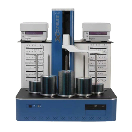
The following section shows and identifies all the important parts of your Xpress XL. These components will be referred to later in the manual; take a few moments to become familiar with them. The main parts of the Xpress XL production system are indicated below (front view). Camera Support Hoist... -
Page 8: Xpress Xl Specifications
The disc spindles hold discs in various stages of processing. There are five full height spindles for holding blank and completed discs, and two shorter reject spindles. All spindles can be lifted off and on for easy disc handling. Xpress XL Specifications • Dimensions: 28.4”... -
Page 9: Installation & Set Up
Installation & Set Up Disc Production Workspace The workspace for the Xpress XL disc production system should be in an environment Important Unpacking free of dust and debris. Contamination can adversely affect production yield, degrade Information Be sure to save all packing the quality of the discs produced, and reduce the life of the equipment. -
Page 10: Checking Your Shipment
7:30 AM to 6:00 PM Pacific Time. Please contact us with any questions or problems unit. Always lift using the during the unpacking, installation, and set up of the Xpress XL disc production sys- handholds in the sides of the units base. -
Page 11: Xpress Xl Contents
Software Key Accessory Box (inside Box #1) Keyboard During unpacking, visually Mouse inspect parts for dents, Cables (Xpress XL Power Cord, and Serial Cable) scratches or other damage. Printer Plates If any parts are damaged, call Microtech’s Customer Arm Assembly... -
Page 12: Xpress Xl Assembly Procedures
Xpress XL Assembly Procedures Base Unit 1. Place base unit on work surface. 2. Set keyboard, mouse, software key, and cables aside for later connection. Drive Enclosure 1. Place drive enclosure on top of base unit (back of enclosure fits flush with back of the base unit.) - Page 13 Disc Printer Option The Xpress XL is designed to handle two printers. A base plate must be installed for each printer. There are left and right base plates labeled - PL = Printer Left; PR = Printer Right. Left and right orientation is determined by facing the front of the Xpress Unit.
- Page 14 8. Repeat procedure for 2nd camera. PRINTERS ARE READY FOR INITIAL TESTING Additional Cables 1. Connect Xpress XL main power cord to port on back of base unit, plug into standard 110v electrical outlet. Connect power cord for drive enclosure power supply into standard 110v electrical outlet.
- Page 15 Setting Up Printers on an Xpress-XL Create a separate Windows printer for each printer. It is best to give them meaningful names like: ‘Rimage Perfect Image Printer - Left’ ‘Rimage Perfect Image Printer - Right’ 1. For each printer created above set the correct port. 2.
-
Page 17: Operation
Operation Once the Xpress XL is set up, test it to make sure everything is operating properly. This chapter covers two quick test procedures. The first is an automated test, that confirms that the system mechanics are working, and that discs can be picked up, dropped and moved around correctly. -
Page 18: The Xpress Xl Desktop
Xpress XL Calibration icon Starts the Xpress XL calibration utility used for calibrating the system. CD-Remote icon Starts the CD-Remote background process and is only necessary should you need to restart the process. -
Page 19: Checking The Xpress Xl Software Configuration
If a printer is installed, it must be identified in the printer settings and options Select the printer names and position on the Xpress XL (left or right) from the drop down menu and set the port in the following field accordingly. (If there’s no printer,... - Page 20 If Your Printer Is A Select This Type On This Port Perfect Image (black-only or color thermal transfer) #1 Rimage Printer COM1 Perfect Image (black-only or color thermal transfer) #2 Rimage Printer COM4 XpressJet II #1 MT XpressJet XpressJet II #2 MT XpressJet K2 (photo retransfer) #1 TEAC...
-
Page 21: Calibrating Xpress Xl
Follow the procedure below to run this test. Calibration Procedures To work properly the Xpress XL needs to be correctly calibrated. If not calibrated propertly you may experience some of the following errors: •... - Page 22 Place a few discs on spindle 4. Start the calibration utility program by double-clicking Caution: Do not shut down the desktop icon Xpress XL Calibration. The calibration utility’s window will open the system if there are any production jobs running (shown below).
- Page 23 • Printer is able to clamp the disc. If the continuous test fails at any point during the cycle - repeat the Xpress XL calibra- tion procedure until results are stable. Disc handling problems are not always repeatable. Accurate calibration is important to achieve reliable operation.
-
Page 24: Placing Discs On Spindles
Placing Discs on Spindles As an automated disc production system, Xpress XL transports discs to various processing stages automatically. The operator’s only physical task is to load blank discs for processing on the input spindle(s) and remove finished discs from the output spindle(s). -
Page 25: Maintenance
Maintenance Microtech Support If you are having problems with your Xpress, before calling Microtech Systems support line please check the following: 1. Check all external connections 2. Check for good power 3. Make sure your system is on a sturdy and level surface 4. - Page 27 Calibration, Printers 16 Checking Software Configuration 12 Installation & Set Up 5 Installing ImageAligner 10 Placing Discs on Spindles 18 Power Up Xpress XL 11 Printer Connections 9 Shutting Down Xpress XL 18 Software Configuration 13 System Parts 3 System Specifications 4...
Need help?
Do you have a question about the Xpress XL and is the answer not in the manual?
Questions and answers