Table of Contents
Advertisement
Quick Links
Advertisement
Table of Contents

Related Manuals for Viessmann AC-Box


Summary of Contents for Viessmann AC-Box
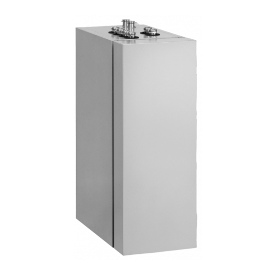
- Page 1 VIESMANN Installation and service instructions for contractors AC-Box Pre-assembled unit for implementing the natural cooling and active cooling functions in conjunction with brine/water heat pumps up to 17 kW For applicability, see the last page AC-Box Please keep safe. 5675 895 GB...
- Page 2 ■ installer or a qualified person authorised by the For replacement, use only spare parts supplied installer. or approved by Viessmann. Regulations to be observed National installation regulations ■ Statutory regulations for the prevention of accidents ■...
-
Page 3: Table Of Contents
Product information ................Information regarding operation ............■ Preparing for installation Hydraulic function diagram ..............Hydraulic connection with on-site pipework ........... Hydraulic connection with AC-Box connection accessories ....Siting and transport requirements ............Transport .................... ■ Installation room requirements ............■... -
Page 4: Information Symbols
Subject to the cool- nection between the heat pump and the AC-Box can ing demand, either the natural cooling or the active be made on site or via the AC-Box connection acces- cooling function starts. sories. -
Page 5: Information Regarding Operation
Information Product information (cont.) Product validity The AC-Box can be used in conjunction with the fol- lowing heat pumps: ■ Vitocal 300-G, types BW/BWC 301.A06 to A17 Vitocal 300-G, types BW/BWC 301.B06 to B17 ■ Vitocal 350-G, type BW/BWC 351.A07 ■... -
Page 6: Preparing For Installation Hydraulic Function Diagram
Plate heat exchanger 1 Component layout inside the appliance: See ■ Plate heat exchanger 2 page 21. Frost stat AC-Box Direction of flow, 3-way diverter valve Contact humidistat 24 V (accessories) – Valve open Flow, heating/cooling circuit or separate cooling... -
Page 7: Hydraulic Connection With On-Site Pipework
Preparing for installation Hydraulic connection with on-site pipework If the AC-Box cannot be installed immediately to the 2. Connect on-site connection lines so that they are left of the heat pump: free of load and torque stress. 1. Install the AC-Box near the heat pump. -
Page 8: Siting And Transport Requirements
Preparing for installation Hydraulic connection with AC-Box connection… (cont.) Primary circuit connection line: Heat pump brine outlet Heat pump Siting and transport requirements Transport Please note Impacts, compression and tensile loads can cause damage to the outside panels of the appliance. -
Page 9: Installation Sequence
Installation sequence Siting the AC-Box 1. Site the AC-Box on a level surface, to the left of the 2. Level the appliance with its adjustable feet. heat pump with no gap between them: See Figs. 2 and 3. Hydraulic connection... -
Page 10: Connection With Ac-Box Connection Accessories
Installation sequence Hydraulic connection (cont.) Connection with AC-Box connection accessories Fig.4 Note Thermally insulate the connections of the AC-Box and the heat pump with vapour diffusion-proof adhesive tape. Hydraulic connection lines: See the following table... -
Page 11: Installing The Contact Humidistat 24 V - (Accessories)
Where the heating/cooling circuit extends over sev- eral rooms with different relative humidity levels, it 1. Fit the contact humidistat outside the AC-Box to the may become necessary to provide several contact flow of the heating/cooling circuit or the separate humidistats. -
Page 12: Additional Connections
Designation Function Internal connec- Page tion, plug "NC signal" Switching signal 230 V~ for switching the AC-Box for the natu- aMAD ral cooling function "AC signal" Switching signal 230 V~ for switching the AC-Box for the ac- aMAE tive cooling function "SC"... - Page 13 Installation sequence Electrical connection (cont.) Removing the front panel and side panel Fig.5...
- Page 14 AC-Box PCB: See page 18. aBAB top of the angled panel. Remove the jumper from plug aBAB Connect the 24 V contact humidistat cable ■ – across terminals X4.1 and X4.2 on the AC-Box PCB: See page 18. Remove the jumper from plug aBAC...
-
Page 15: Overview Of Electrical Connections
230 V~ aMY] aMY] aMG fÖ 230 V~ aBY] aBY] aBY] Fig. 7 AC-Box PCB Contact humidistat 24 V , 10 mA: See aMAD – NC signal 230 V~: See page 16. page 18. aMAE aBAC AC signal 230 V~: See page 16. -
Page 16: Switching To Heat Pump Control Unit (Nc / Ac Signal)
Shutdown signal for heat pump 230 V~ The frost stat and contact humidistat 24 V are con- – nected to the AC-Box. The shutdown signal must be connected at the heat pump control unit to ensure the compressor stops when these safety devices respond. - Page 17 Electrical connection (cont.) L´ GNYE Fig.9 Note Plug is plugged into the AC-Box PCB at the fac- tory. Cross connect PCB inside the heat pump control unit X1 Earth conductor terminal strip X3 Terminal strip for message and safety connec- tion AC-Box PCB "SC"...
-
Page 18: Contact Humidistat 24 V
X4.1 Fig.10 Contact humidistat (accessories) 24 V , 10 mA – X4 Low voltage terminal strip on the AC-Box PCB Additional frost stat (accessories) 1. Connect the frost stat. 2. Remove the jumper from plug : See page 15. aBAB 151B Fig.11... -
Page 19: Contact Humidistat Signal 24 V
We recommend connecting the power supply for the The appliance and pipework must be connected ■ AC-Box at the power supply of the heat pump control to the equipotential bonding of the building. unit. Connection to the same fuse provides additional pro-... -
Page 20: Connections On Plug Fö
GNYE Fig.14 Power cable 1/N/PE 230 V/50 Hz ■ Length approx. 2.5 m ■ Connected to the AC-Box at the factory via plug and routed to the outside; marked fÖ "Mains" Closing the AC-Box Fit in reverse order to Fig. 5 on page 13. -
Page 21: Upkeep
Upkeep Internal components Fig.15 2-way valve V1 High efficiency circulation pump M1 Plate heat exchanger 1 Plate heat exchanger 2 2-way valve V2 2-way valve V6 2-way valve V5 High efficiency circulation pump M2 2-way valve V7 3-way diverter valve V4 2-way valve V3 Frost stat... -
Page 22: Parts Lists Overview Of Assemblies
Parts lists Overview of assemblies The following details are required when ordering parts: ■ Serial no. (see type plate ■ Assembly (from this parts list) ■ Position number of the individual part within the assembly (from this parts list) Fig.16 Type plate Hydraulic assembly Casing assembly... -
Page 23: Parts Not Shown
The following details are required when ordering parts: ■ Serial no. (see type plate in Fig. 16) ■ Position number of the part (from this parts list) Pos. Part 0005 AC-Box installation and service instructions 0006 Touch-up paint stick, Vitosilver 0007 Touch-up spray paint, Vitosilver... -
Page 24: Casing
Parts lists Casing 0002 0009 0014 0014 0015 0015 0003 0012 0004 0005 0011 0005 0011 0016 0013 0010 0007 0006 0008 0006 0008 0008 0008 0001 Fig.17... - Page 25 Parts lists Casing (cont.) Pos. Part 0001 Front panel 0002 Side panel, left 0003 Side panel, right 0004 Retaining bracket 0005 Profiled panel (Z profile) 0006 Front panel retainer 0007 Elbow 0008 Adjustable foot 0009 Diaphragm grommets (set) 0010 Threaded pipe clip 28 mm, M6 (2 pce) 0011 Threaded pipe clip...
-
Page 26: Electrical Equipment
Parts lists Electrical equipment 0008 0010 0002 0007 0001 0006 0003 0013 0004 Fig.18... - Page 27 Parts lists Electrical equipment (cont.) Pos. Part 0001 Terminal box 0002 Plug 0003 Diaphragm grommet 36 mm 0004 Power cable 0006 Frost stat connecting cable 0007 Connecting cable for switching 0008 Connecting cable, shutdown signal for heat pump 0010 Strain relief fittings 0013 Plug Parts not shown...
-
Page 28: Hydraulics
Parts lists Hydraulics 0023 0012 0022 0003 0018 0024 0021 0021 0021 0016 0017 0021 0021 0004 0003 0021 0021 0021 0020 0021 0021 0003 0004 0007 0003 0021 0021 0021 0021 0010 0021 0021 0003 0025 0004 0023 0003 0022 0025 0021... - Page 29 Parts lists Hydraulics (cont.) Pos. Part 0001 High efficiency circulation pump M1 with plug sÖA 0002 High efficiency circulation pump M2 with plug sÖB 0003 2-way motorised ball valve 0004 Ball valve G 1 with 2-way motorised ball valve ¼ 0005 3-way diverter valve 0006...
-
Page 30: Connection Set
Parts lists Connection set 0002 0001 0004 0003 Fig.20... - Page 31 Parts lists Connection set (cont.) Pos. Part 0001 Connection line, secondary circuit to heat pump 0002 Connection line, secondary circuit from the heat pump 0003 Connection line, primary circuit from the heat pump 0004 Connection line, primary circuit to the heat pump...
-
Page 32: Connection And Wiring Dia
Connection and wiring diagram Connection and wiring diagram X4.1 X4.2 X4.8 X4.9 X4.7 aBY] X3.8 230V X3.9 aBY] aMY] aMY] aBY] Fig.21 Note Contact humidistat 24 V (accessory) – Earth connection not shown. Shutdown signal for heat pump 230 V~ NC signal 230 V~ Power supply 1/N/PE 230 V/50 Hz AC signal 230 V~... -
Page 33: Specification
30 to 60 ■ Test pressure Max. 4.5 Max. 0.45 Hydraulic connections Primary circuit flow/return (AC-Box brine inlet/outlet) ¼ Flow/return, heating/cooling circuit, separate cooling circuit ¼ Connection line, primary circuit from/to the heat pump (brine) ¼ Connection line, secondary circuit from/to the heat pump (heating... -
Page 34: Declaration Of Conformity
Declaration of conformity Declaration of conformity We, Viessmann Werke GmbH & Co KG, D-35107 Allendorf, confirm as sole responsible body that the product AC-Box complies with the following standards: EN 13 779 EN 60 335-1:2002-02 + A11:2004 + A1:2004 +... -
Page 35: Keyword Index
Heating water inlet 3-way diverter valve........6, 21, 29, 33 – AC-Box..............7 – Heat pump..............7 Heating water outlet AC-Box connection accessories......7, 10 – AC-Box..............7 AC signal............6, 15, 32 – Heat pump..............7 Active cooling............. 12 Heat pump brine inlet........... 7 Additional connections.......... - Page 36 – Low voltage..........15, 18, 19 – Message and safety connections......17 – Neutral conductor............16 Applicability Serial No.: 7554884 Viessmann Werke GmbH&Co KG Viessmann Limited D-35107 Allendorf Hortonwood 30, Telford Telephone: +49 6452 70-0 Shropshire, TF1 7YP, GB Fax: +49 6452 70-2780 Telephone: +44 1952 675000 www.viessmann.com...
Need help?
Do you have a question about the AC-Box and is the answer not in the manual?
Questions and answers