
Related Manuals for Arthur Grillo DPC200-MOD


Summary of Contents for Arthur Grillo DPC200-MOD
- Page 1 Installation and operation manual DPC200-MOD DIFFERENTIAL PRESSURE / VOLUME FLOW CONTROLLER Low pressure sensor with PI-control and Modbus RTU digialisation Issue: 08/2019 Doc.-no.: DPC200-MOD_02_EN...
- Page 2 Arthur Grillo GmbH. This applies in particular to duplications, trans- lations, microfilming and storage and processing in electronic systems.
-
Page 3: Table Of Contents
Used pictograms and symbols General notes Product description Type plate Intended use Functional description Installation Dimensions Wall mounting Start up Overview DPC200-MOD Schematic view inside Pressure connections Electrical connection Zero adjustment Operation Start menu Menu structure Start up & modbus control Measuring mode... -
Page 4: General Safety Instructions
GENERAL SAFETY INSTRUCTIONS General safety instructions 1.1 Signal words for safety instructions The safety instructions in this operation manual are designed to prevent hazards. They can be found in the operation manual before an operation / task / activity is described, which can entail a possible hazard. -
Page 5: Product Description
PRODUCT DESCRIPTION Product description The DPC200-MOD is a measuring device for low pressure of inert gas, particularly of air. The device has both a 0...10 V signal output as well a Modbus RTU interface for digital communication. 2.1 Type plate... -
Page 6: Installation
INSTALLATION Installation The differential pressure controller DPC200-MOD is designed for wall mounting. • The mounting surface must be solid enough and vibration-free. • The environment has to fulfill the ambient climatic conditions as given in the technical data. CAUTION Material damage... -
Page 7: Start Up
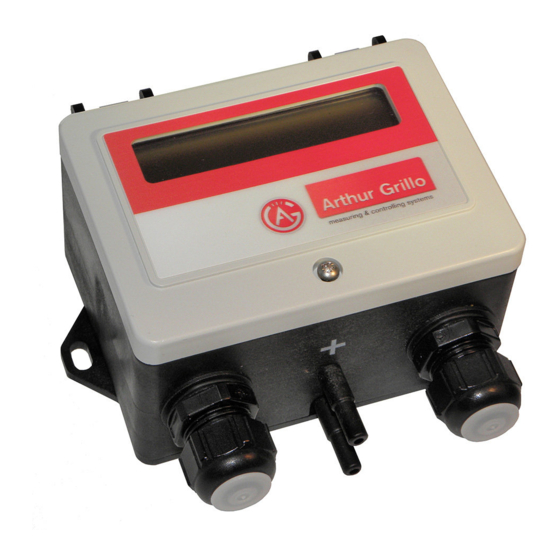
START UP Start up 4.1 Overview DPC200-MOD Front cover Cable gland Pressure connection 1 Pressure connection 2 Cable gland 4.2 Schematic view inside Button 1 Button 2 Button B1 and B2 serve for the operation of the menu 4.3 Pressure connections Connect all pressure connections properly with plastic tubing (inner diameter 5 or 6 mm). -
Page 8: Electrical Connection
MODBUS OPERATION 4.4 Electrical connection DPC200-MOD + 15...30 Vdc or 24 Vac (±15%) supply - GND + 0...10 Vdc output ΔP - GND MODBUS Unscrew screws of the front cover. Open front cover. Use M16 cable glands for connecting wiring to terminals. -
Page 9: Menu Structure
OPERATION 5.2 Menu structure ∆P control mode ∆P = 150 Pa Press B1 about 2 seconds to start menu. menu Press B2 button Press B1 modbus modbus >off< >on< button Press B2 button Press B2 button Press B1: Reset Press B2: Select modbus address Press B1: Confirm Display flashes once... -
Page 10: Start Up & Modbus Control
OPERATION 5.3 Start up & modbus control Display Action controlling mode Start menu: Press button B1 approx. two seconds ΔP = 150 Pa menu Press button B2 to get to the next menu item Press button B1 to switch between: on <=> off Press button B2 to modbus get to the next menu item If selected parameter = ON... -
Page 11: Control Mode
OPERATION 5.5 Control mode Display Action controlling mode Start menu: Press button B1 approx. two seconds ΔP = 150 Pa menu Press button B2 to get to the next menu item Press button B1 to switch between: modbus on <=> off Press button B2 to get to the next menu item Press button B1 to switch between: unit metric metric <=>... -
Page 12: Adjustable Parameters
OPERATION OPERATION If selected parameter = volume flow than follows the additional input for the k-factor Button B1: reset value fan k-factor Button B2: set value k = 70 Button B1: confirm value, display flashes once Press button B2 to get to the next menu item 5.6 Adjustable parameters Parameter Selection or parameter range... -
Page 13: Threshold Calculation
The DPC200-MOD has two connection terminals for the Modbus, which are designated A and B. The Modbus line of the DPC200-MOD can be terminated via a further jumper. This jumper can be plugged into two positions: terminated or not terminated. The terminating resistor is 120 Ohm. - Page 14 OPERATION Menu features: The DPC200-MOD menu has been extended by four more points. modbus baud rate modbus Modbus func- communication 7200 / 9600 / 14400 / ON / OFF tion on and off baud rate 19200 / 38400 / 57600...
- Page 15 OPERATION Function Code 0x04: Function Code 0x06: request: request: 05 04 00A0 0001 306C 05 06 00C0 0001 49B2 ID of the device. ID of the device. Function code. Function code. 00A0 Data address to be read. 00C0 Data address to be described. 0001 Number of registers to be read.
-
Page 16: Maintenance
WARRANTY & SUPPORT Maintenance The DPC200-MOD contains no wearing or consumable parts. Servicing is not required. On request, Arthur Grillo GmbH offers an annual calibration with factory certificate. For information, please contact: Arthur Grillo GmbH Phone: +49 21 02 - 47 10 22... -
Page 17: Specifications
SPECIFICATIONS 10. Specifications Mode: Measuring or controlling mode Measuring medium: Air or inert gases Measuring principle: Silicon diaphragm with spring and differential transformer Measuring unit: Pa / inH O oder m /h oder cfm Lowest span: 0...50 Pa Highest span: 0...6000 Pa Adjustable controlling parameters:... -
Page 18: Ce-Labelling
CE-LABELLING 10.1 CE-labelling As an electric device the DPC200-MOD falls within the scope of the directive 2004/108/ EG (EMV-directive). In the scope of the EMV-directive the following norms were applied: DIN EN 61000-6-2:2006-03 Electromagnetic compatibility (EMC) - Part 6-2: Generic...
Need help?
Do you have a question about the DPC200-MOD and is the answer not in the manual?
Questions and answers