Table of Contents
Advertisement
Quick Links
FOR YOUR SAFETY
Do not store or use gasoline or other flammable vapors or
liquids in the vicinity of this or other appliance.
302 Spencer Lane • P.O. Box 5369
PN 30A170 rev Jan2008
ULTRAFRYER GAS FRYER
MODEL F-P-30-14 / 18 / 20
OPERATION INSTRUCTIONS
(800) 525-8130 • (210) 731-5000 • Fax: (210) 731-5099
www.ultrafryer.com
WARNING
Improper Installation, adjustment, alteration, service, or main-
tenance can cause property damage, injury, or death. Read the
installation, operating, and maintenance instructions thoroughly
before installing or servicing this equipment.
1
San Antonio, Texas 78201
Advertisement
Table of Contents
Troubleshooting

Subscribe to Our Youtube Channel
Related Manuals for ULTRAFRYER Systems F-P-30-14


Summary of Contents for ULTRAFRYER Systems F-P-30-14
- Page 1 ULTRAFRYER GAS FRYER MODEL F-P-30-14 / 18 / 20 OPERATION INSTRUCTIONS WARNING FOR YOUR SAFETY Improper Installation, adjustment, alteration, service, or main- Do not store or use gasoline or other flammable vapors or tenance can cause property damage, injury, or death. Read the liquids in the vicinity of this or other appliance.
- Page 2 PREFACE This Manual was written and published by the Engineering Department, Ultrafryer Systems for use by personnel who will operate a Model P30 Gas Fryer in a commercial cooking environment. This appliance is intended for professional use and is to be operated by qualified personnel.
-
Page 3: Table Of Contents
TABLE OF CONTENTS GENERAL INFORMATION Warranty..............6 Safety . - Page 4 TABLE OF CONTENTS..Continued PREVENTIVE MAINTENANCE & TROUBLESHOOTING Preventive Maintenance ........... . 24 Troubleshooting .
-
Page 5: General Information
GENERAL INFORMATION PN 30A170 rev Jan2008... -
Page 6: Warranty
Ultrafryer Systems for first year failures only. The cost of labor to install the replacement vat will be covered by Ultrafryer Systems for vats, which fail within twelve (12) months from the date of initial start up. Labor for vat replacements after the first year is the responsibility of the owner (2) Vats that fail within the second through fifth year will be exchanged at $250.00 FOB San Antonio. -
Page 7: Safety
B. SAFETY The major safety concern associated with the Ultrafryer Gas Fryer is burns from hot shortening. In order to prevent serious burns, good houskeeping habits are required. The floor in front of and the area around the fryer should be kept clean and dry. -
Page 8: Operating Controls Location
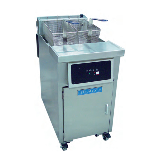
E. OPERATING CONTROLS LOCATION MODEL PAR30 GAS FRYER Gas Regulator and Shutoff Valve High Limit Burner Docking Connection Main Drain Valve PN 30A170 rev Jan2008... -
Page 9: Operating Controls
W.C. ; minimum inlet gas required, orifice size; and type of gas. This data is essential for proper identification when com- nicating with ULTRAFRYER SYSTEMS or requesting special parts or information. The rating plate is located on the inside of the Service Access door. -
Page 10: Inlet Gas Line Sizing
The Flexible Gas Line used to connect the gas manifold to the building gas supply line must be rated for the BTU/Hr (MJ/Hr) designated for the Fryer. Flexible gas lines and their ratings stocked by Ultrafryer Systems are listed below:... -
Page 11: Pre-Installation
PRE-INSTALLATION PN 30A170 rev Jan2008... -
Page 12: General
A. GENERAL: Safe and satisfactory operation of a Model PAR30 gas fryer depends on its proper installation. Installation must conform to local codes or, in the absence of local codes, with the current National Fuel Gas Code ANSI Z223.1 (latest edi- tion). -
Page 13: Receiving & Installing
RECEIVING & INSTALLING PN 30A170 rev Jan2008... -
Page 14: Unpacking
NOTE: CONNECT-IT inc. 3⁄4" (19mm), 1" (25mm) and 1 1⁄4" (32mm) flexible gas hose 4 feet long (1219mm) with a quick disconnect coupling on one end is available from Ultrafryer Systems under PN 24322 (3⁄4" (19mm) hose), PN 24323 (1" (25mm) hose) and PN 24456 (1 1⁄4" (32mm) hose). These hoses are euipped with a fusible link, which melts at 361°F (183ºC) that will SHUT OFF the gas supply when it melts. -
Page 15: Gas Connection
D. GAS CONNECTION: The gas supply (service) line must be the same size or greater than the inlet line of the appliance. THE GAS SUPPLY LINES MUST BE SIZED TO ACCOMMODATE ALL THE GAS FIRED EQUIPMENT THAT MAY BE CONNECTED TO THAT SUPPLY. -
Page 16: Cooking Computers
F. Cooking Computers All fryers from Ultrafryer are shipped with the applicable manual for the cooking computer or computers that are specific to that fryer. The following list shows the cooking computer types and their related manuals. NOTE: The appearance of a given cooking computer’s control panel may vary slightly depending upon the style of fryer on which the computer is installed. - Page 17 Ultrastat 21 Cooking Computer (refer to Manual P/N 30A189; French Version 30A189 FR) Ultrastat 11 Cooking Computer (refer to Manual P/N 30A191; French Version 30A191 FR) PN 30A170 rev Jan2008...
-
Page 18: Initial Start-Up
INITIAL START-UP PN 30A170 rev Jan2008... -
Page 19: Cleaning
Initial calibration or adjustment is the responsibility of the customer and will not be covered by the Ultrafryer Systems warranty. NOTE: Calibration and adjustments must be performed by qualified personnel. -
Page 20: Abbreviated Operating Instructions
ABBREVIATED OPERATING INSTRUCTIONS PN 30A170 rev Jan2008... -
Page 21: General
A. GENERAL: This gas fryer is equipped with a shortening filter system which is to be operated and cleaned according to the FRYER OPERATION section of this manual. SHORTENING: Use a high quality shortening to achieve a consistent quality product as well as a long term savings. SHORTENING TEMPERATURE: Most products should be cooked with a shortening temperature about 350˚F (177˚C);... -
Page 22: Boiling Out Fryer
E. BOILING OUT FRYER: The fryer should be BOILED OUT every 7 DAYS to remove carbon buildup and other encrusted materi- als. Add the amount of boil out compound to the fryer as prescribed in the cleaning manual provided by the chemical supplier and follow instructions for boiling out a fryer in the “General Filtration Procedures”... -
Page 23: Preventive Maintenance & Troubleshooting
PREVENTIVE MAINTENANCE & TROUBLESHOOTING PN 30A170 rev Jan2008... -
Page 24: Preventive Maintenance
Determine that the blower is operating. TROUBLESHOOTING CHART: Should a problem occur that cannot be corrected after performing the above CHECKS, contact an AUTHORIZED repairman and/or Ultrafryer Systems Systems Customer Service 1-800-525-8130 and provide the information acquired while performing these checks. - Page 25 TROUBLESHOOTING CHART ITEM PROBLEMS POSSIBLE SOLUTIONS A. Check the Blower air pressure Switch by temporarily disconnecting the two (2) air switch wires and connecting them together. If the IGNITOR sparks when these wires are connected, the air pressure switch is defective and it will Main burner will not ignite.
- Page 26 CLEANING PN 30A170 rev Jan2008...
-
Page 27: Cleaning
CLEANING - Any item of equipment operates better and lasts longer when it is kept clean and properly maintained. The Gas Fryer is no exception. In order for this fryer to provide years of trouble-free service, it must be CLEANED and MAINTAINED according to instruc- tions herein and at the intervals listed below: TO ASSURE PRODUCING A QUALITY PRODUCT WHILE PROLONGING THE LIFE EXPECTANCY OF WARNING!!! -
Page 28: Filter Tub Assembly & Installation
FILTER TUB ASSEMBLY & INSTALLATION PN 30A170 rev Jan2008... -
Page 29: Filter Tub Assembly
NOTE: The following applies only to those fryers that are equipped with a hard dock filtration assembly from Ultrafryer Systems. FILTER TUB ASSEMBLY - ENSURE all components of the filter tub have been thoroughly cleaned and that the Filter Screen has been assembled;... - Page 30 TECHNICAL ASSISTANCE, ORDERING INFORMATION PN 30A170 rev Jan2008...
-
Page 31: Technical Assistance
Carriers must be notified immediately and freight inspections must be requested from the carrier. Ultrafryer Systems can and will gladly assist you in prepar- ing and processing of the necessary claims only if proper notification has been accomplished on the carrier deliv- ery document. - Page 32 RECOMMENDED SPARE PARTS PN 30A170 rev Jan2008...
-
Page 33: Recommended Spare Parts
RECOMMENDED SPARE PARTS: To minimize downtime on the Model PAR30 gas fryer upon failure of a component part, at least one (1) of the following items should be kept as a spare part in the local area: MODEL PAR25 GAS FRYER RECOMMENDED SPARE PARTS LISTING Description Manufacturer’s Part Number... -
Page 34: Parts Identification
PARTS IDENTIFICATION PN 30A170 rev Jan2008... - Page 35 PARTS IDENTIFICATION - Locate the part on the following sketches and note the index number i.e, 3, 6, etc; then obtain the part number and description for that index number on the page facing the sketches. Use that part number when ordering a replacement part.
- Page 36 ULTRAFRYER MODEL PAR30 GAS FRYER REAR VIEW Note: Fryer shown is 14” Par30 with Filtration. For information on other fryer models, contact Ultrafryer Customer Service. � � � � � �� �� �� �� Note: Parts listed below are for 14” Par30 with Filtration. For information on other fryer models, contact Ultrafryer Customer Service. ITEM DESCRIPTION Model SMD 1204 Air Pressure Switch...
- Page 37 � � � ELECTRONIC THERMOSTAT PN 12B077 � ITEM DESCRIPTION Electronic Thermostat Face Plate 18A070 Temperature Probe 18A276 Electronic P14 Thermostat Bracket 19B174 Electronic Thermostat Knob 22A169 PN 30A170 rev Jan2008...
- Page 38 PAR30 EZ DOCK FILTER TUB ASSEMBLY 14" With Micromesh Filter PN 12B112 14" With Magnepad Filter PN 12B177 � ITEM DESCRIPTION Filter Tub Scraper 12567 � Micromesh S/S Filter Screen Assembly with 12B113 StandPipe & Docking Assembly � Magepad Magnesol Impregnated Filter Pad 12B178 with Standpipe and Docking Assembly Wash Down Hose Assembly...
- Page 39 FILTER SCREEN ASSEMBLY ITEM DESCRIPTION Replacement Frame Set 21A284 Replacement “Upper” Screen 21A285 Replacement Baffle Assembly 21A286 Replacement “Lower” Screen 21A287 � �� � �� � � � �� STANDPIPE CLIP, BAFFLE AND MAGNEPAD ASSEMBLY PN 12B178 ITEM DESCRIPTION 1/2" (13mm) Black Iron Close Nipple 24003 3/8"(10mm) x 7"...
- Page 40 ULTRAFRYER MODEL PAR30 GAS FRYER AUTOMATIC VAT CLEANER � � 14” PN 12B157 � � � � � � �� ����� ITEM DESCRIPTION Proximity Actuator Sensor 18A059 Cool II Handle 22734 1⁄2” (13mm) HH-2236 SQ Spray Nozzle 22A111 1⁄2" (13mm) x 90˚ Black Iron Elbow 24007 1⁄2"...
- Page 41 WIRING DIAGRAMS PN 30A170 rev Jan2008...
-
Page 42: Wiring Diagrams
WIRING DIAGRAM - Since minor wiring changes may occur in the future, USE the diagram pasted to the fryer for circuit tracing and/or troubleshooting a gas fryer. PN 30A170 rev Jan2008...
Need help?
Do you have a question about the F-P-30-14 and is the answer not in the manual?
Questions and answers