
Subscribe to Our Youtube Channel
Related Manuals for ULTRAFRYER Systems Ultrastat 11


Summary of Contents for ULTRAFRYER Systems Ultrastat 11
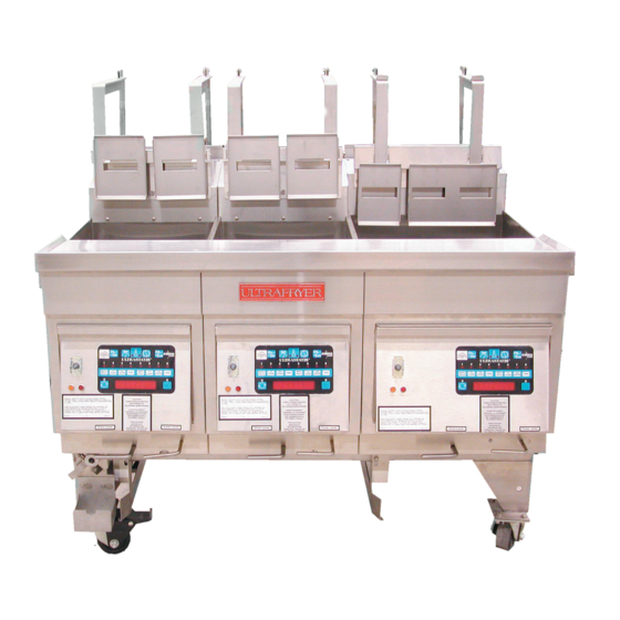
- Page 1 ELECTRIC AND GAS FRYER AUTOMATIC BASKET LIFT SYSTEM Operating Instructions 302 Spencer Lane • P.O. Box 5369 San Antonio, Texas 78201 (800) 525-8130 • (210) 731-5000 • Fax: (210) 731-5099 www.ultrafryer.com 30A081...
- Page 2 Ultrafryer systems, Inc., offers two (2) versions of the Automatic Basketlift system. One is manufactured by SKF Motion Tech- nologies and the other is fabricated by Ultrafryer Systems. The Physical difference between the two can be determined by the top cap of the Basketlift Box assembly.
-
Page 3: Table Of Contents
Ultrastat 11 Basket Lift Operation ........ -
Page 4: General Information Page
GENERAL INFORMATION Page 1 of 26 30A081... -
Page 5: Warranty
A. WARRANTY BASKET LIFT SYSTEM LIMITED WARRANTY WARRANTY- SKF Motion Technologies warrants to the original purchaser of a Model S5420212 Automatic Basket Lift System, sold within the United States, it’s territories and Canada, that it will be free of defects in material and workmanship for a period of one (1) year from the date the Basket Lift System was placed in operation. -
Page 6: Safety
Basket Lift system. This Basket Lift system is applicable for ALL three (3) currently produced vessel sizes; 14" (356mm), 18" (457mm) and 20" (508mm) Gas or Electric Ultrafryer Systems, Inc. -
Page 7: Operating Instructions
OPERATING INSTRUCTIONS Page 4 of 26 30A081... -
Page 8: General
The Automatic Basket Lift System can be used on any Ultrafryer Systems Electric or Gas fryer equipped with an Ultrastat 11, 21 or 25 cooking computer. When the fryer’s 120 Volt electrical plug is connected to the 120 Volt power source, BOTH (LH &... -
Page 9: Ultrastat 11 Basket Lift Operation
In order to operate the Basket Lift system, 120 Volts must be applied to the fryer, the fryer’s ON/OFF switch and Ultrastat 11 computer MUST be in the ON position, and shortening temperature MUST be at the PRE-SET (COOKING) TEMPERATURE for the product to be cooked. -
Page 10: Ultrastat 21 Basket Lift Operation
D. ULTRASTAT 21 BASKET LIFT OPERATION The Basket Lift Arms will RISE to their UPWARD position when 120 Volts is applied to the fryer and when the fryer and computer are turned ON, it will place the fryer in the MELT MODE. While in the MELT MODE, the computer will cycle the fryer’s heat mechanism ON and OFF to gradually and safely raise the shortening temperature to the programmed cook temperature. -
Page 11: Abbreviated Operation Steps
75˚F NOTE: THE SHORTENING RELEASE TEMPERATURE IS FACTORY SET FOR A LOW [Room Temperature < (24˚C 135˚F (57˚C )>] OR A HIGH [ ] RELEASE TEMPERATURE AS REQUESTED AT THE TIME OF THE PURCHASE ORDER. When the fryer is taken out of the shortening MELT MODE, the computer will turn the fryer’s heat mechanism ON until the PRE-SET(COOKING) temperature is reached and READY appears on the display. -
Page 12: Maintenance
MAINTENANCE Page 9 of 26 30A081... -
Page 13: General
GENERAL - Maintenance or repair of components located on the REAR of the fryer may become necessary in which case the Basket Lift system will have to be removed to provide access to the rear of the fryer. The ONLY maintenance which is authorized on the Basket Lift system is the adjustment of the Basket Lift Arm height. - Page 14 FIGURE 1 ������ ��� ������ ���� ��� ������ ������ ����� ������ ������ ����� FIGURE 3 �������� ��������� ����� ���� ���� ���� ���� ������ ��� ������ ��� ������� ������ ������ ����� ��� ����� ����� ��� ����� ����� ������ ������ ������ ������ ����������...
-
Page 15: Technical Assistance & Ordering Information
TECHNICAL ASSISTANCE & ORDERING INFORMATION Page 12 of 26 30A081... -
Page 16: Technical Assistance
Carriers must be notified immediately and freight inspections must be requested from the carrier. Ultrafryer Systems can and will gladly assist you in preparing and processing of the necessary claims only if proper notification has been accomplished on the carrier delivery document. -
Page 17: Parts Identification
PARTS IDENTIFICATION Page 14 of 26 30A081... - Page 18 PARTS IDENTIFICATION - Locate the part on the following sketches and note the index number i.e, 3, 6, etc; then obtain the part number and description for that index number on the page facing the sketches. Use that part number when ordering a replacement part.
- Page 19 PARTS IDENTIFICATION - Locate the part on the following sketches and note the index number i.e, 3, 6, etc; then obtain the part number and description for that index number on the page facing the sketches. Use that part number when ordering a replacement part.
- Page 20 ITEM DESCRIPTION PART # Replacement Automatic Basket System - 14" SA / 14” Only Bank ***SEE NOTE BELOW*** 12B578 Replacement Automatic Basket System - 14" Mixed Bank ***SEE NOTE BELOW*** 12B579 Replacement Automatic Basket System - 18" SA / Bank ***SEE NOTE BELOW*** 12B580 Basket Lift Receptacle Bracket 19B536...
-
Page 21: Wiring Diagrams
WIRING DIAGRAMS Page 18 of 26 30A081... - Page 22 WIRING DIAGRAM Applicable Only To Electric Fryers With U25 Controllers WITH Basket Lifts Page 19 of 26 30A081...
- Page 23 WIRING DIAGRAM Applicable Only Electric Fryers With U21 Controllers WITH Basket Lifts Page 20 of 26 30A081...
- Page 24 WIRING DIAGRAM Applicable Only To Electric Fryers With U22 Controllers WITH Basket Lifts Page 21 of 26 30A081...
- Page 25 WIRING DIAGRAM Applicable Only To Gas PAR-2 Bank or PAR-2/3 Stand Alone Fryers With U25 Controllers WITH Basket Lifts Page 22 of 26 30A081...
- Page 26 WIRING DIAGRAM Applicable Only To Gas PAR-3 Bank Fryers With U25 Controllers WITH Basket Lifts Page 23 of 26 30A081...
- Page 27 WIRING DIAGRAM Applicable Only To Gas PAR-2/3 Fryers With U21 Controllers WITH Basket Lifts Page 24 of 26 30A081...
- Page 28 WIRING DIAGRAM Applicable Only To Gas PAR-2/3 Fryers With U22 Controllers WITH Basket Lifts Page 25 of 26 30A081...
- Page 29 THIS PAGE INTENTIONALLY BLANK Page 26 of 26 30A081...
Need help?
Do you have a question about the Ultrastat 11 and is the answer not in the manual?
Questions and answers