Table of Contents
Advertisement
Quick Links
J1000
1,000 Watt
AM Broadcast
Transmitter
Installation and Operation Manual
Issue 7.0 .................................. 03 June 2020
Nautel Limited
10089 Peggy's Cove Road,
Hackett's Cove, NS, Canada B3Z 3J4
T.877 6 nautel (628835) or +1.902.823.2233
F.+1.902.823.3183 info@nautel.com
U.S. customers please contact:
Nautel Inc.
201 Target Industrial Circle, Bangor ME 04401
T.877 6 nautel (628835) or +1.207.947.8200
F.+1.207.947.3693 info@nautel.com
e-mail: support@nautel.com
www.nautel.com
Copyright 2020 NAUTEL. All rights reserved.
Advertisement
Table of Contents
Troubleshooting

Related Manuals for Nautel J1000


Summary of Contents for Nautel J1000
- Page 1 Hackett's Cove, NS, Canada B3Z 3J4 T.877 6 nautel (628835) or +1.902.823.2233 F.+1.902.823.3183 info@nautel.com U.S. customers please contact: Nautel Inc. 201 Target Industrial Circle, Bangor ME 04401 T.877 6 nautel (628835) or +1.207.947.8200 F.+1.207.947.3693 info@nautel.com e-mail: support@nautel.com www.nautel.com Copyright 2020 NAUTEL. All rights reserved.
- Page 3 If the Buyer receives a replacement module, as part of Nautel’s module exchange program, the old module must be returned to Nautel within 30 days of receipt of the new module, at the buyers expense. If the old module is not received after 30 days, the customer will be invoiced. The buyer is responsible for installing the replacement/repaired module in the transmitter.
- Page 4 Buyer and the third party provider. 13. Nautel provides telephone and email support for its products for the life of the product at no charge. After the warranty period, parts and on-site support for the equipment are offered at a rate to be determined upon request.
- Page 5 When the warranty has expired, a charge of 80% of the list price for all exchanged modules is made. If the faulty module is returned to Nautel within 30 days, a credit is issued reducing this charge by one half to 40% of the list price.
- Page 7 A NOTE denotes important information pertaining to an operating procedure, condition, statement, etc., which is essential to highlight. A NOTE may precede or follow the text to which it applies. J1000 Installation and Operation Manual Issue 7.0 Safety Information Page 1...
- Page 8 ‘BeO’ in the part’s description. DO NOT cut, crush or grind devices because the resulting dust may be HAZARDOUS IF INHALED. Unserviceable devices should be disposed of as harmful waste. J1000 Installation and Operation Manual Issue 7.0 Page 2...
- Page 11 NOTICE FOR HD RADIO USERS ONLY SALE OR DISTRIBUTION OF THIS DEVICE REQUIRES A LICENSE FROM IBIQUITY DIGITAL CORPORATION. (Contact licensedproductnotification@xperi.com)
-
Page 13: Table Of Contents
2.1.18.2 Digital Operation (External Phase Component) 2.1.18.3 Digital Operation HD Radio 2.1.19 Audio Pass Band Selection 2.1.20 External Interlocks 2.1.21 Remote Control Circuits 2.1.21.1 On/Off Control 2.1.21.2 Main Exciter Selection 2.1.21.3 Preset Power Level Selection J1000 Installation and Operation Manual Jun 03.20... - Page 14 2.2 INSTALLATION 2-15 2.2.1 Accepting the Shipment 2-15 2.2.2 Unpacking Instructions 2-15 2.2.3 Visual Inspection 2-16 2.2.4 RF Output Connector 2-20 2.2.5 Cabinet Installation 2-20 2.2.6 Installing RF Power Modules 2-22 2.2.7 Interconnect Wiring 2-22 J1000 Installation and Operation Manual Jun.03.20...
-
Page 15: Introduction
Exciter Front Panel 3.5.2 Remote Interface PWB 3.5.3 RF Synthesizer PWB 3.5.4 Miscellaneous Exciter 3.5.5 RF Power Module DIAGNOSTIC DISPLAY 3-14 3.6.1 Pushbutton Switches 3-14 3.6.2 Main Screen 3-14 3.6.2.1 Transmitter Status Bar 3-14 J1000 Installation and Operation Manual Jun 03.20... - Page 16 4.3.6.5 Dc Current Cutback SYSTEM LEVEL TROUBLESHOOTING 5.1 GENERAL 5.2 SCHEDULED MAINTENANCE 5.2.1 Cleaning the J1000 5.2.2 Checking Hardware 5.2.3 Battery Replacement 5.3 CORRECTIVE MAINTENANCE 5.3.1 On-Air Troubleshooting 5.3.1.1 Remote Troubleshooting 5.3.1.2 Local Troubleshooting 5.3.2 Off-Air Troubleshooting J1000 Installation and Operation Manual Jun.03.20...
- Page 17 Exciter Panel – Control Section Controls and Indicators Remote Interface PWB Controls and Indicators 3-10 RF Synthesizer PWB Controls and Indicators 3-12 Miscellaneous Exciter Controls and Indicators 3-13 RF Power Modules Controls and Indicators 3-13 Troubleshooting and Replacement Tips J1000 Installation and Operation Manual Jun 03.20...
- Page 18 Exciter/Control Assembly (Unit 1) RF Power Module (Left-Hand Side View) RF Output with Positive Peak Limiting Modulated RF Output with Audio Dump Distortion Adjustment Partial Rear View of J1000 (showing RF Power Modules) 5-11 Removing Cooling Fans from Exciter/Control Assembly 5-18...
- Page 19 Control Record Issue Date Reason 03 June 2020 Release 7 of J1000 (NARA40F) J1000 Installation and Operation Manual Jun 03.20...
-
Page 21: Purpose And Scope Of Manual
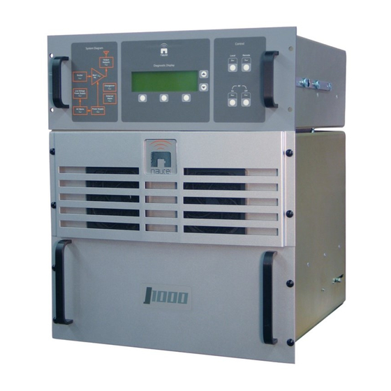
GENERAL INFORMATION 1.1 INTRODUCTION The J1000 is a medium wave, 1,000 watt AM broadcast transmitter. It is entirely solid state and is HD Radio™ and DRM compatible. The transmitter is shown in Figure 1-1. Two completely independent and redundant signal chains from the LVPS output to the RF output filter reduce the amount of time the transmitter is off-air. -
Page 22: J1000 Transmitter
Figure 1-1 J1000 Transmitter J1000 Installation and Operation Manual Page 1-2 Issue 7.0 Section 1 General Information... - Page 23 Testing and maintenance Dc power supply (fixed) 24 V, 1 A Testing and maintenance Torque wrench Capable of providing five Installing power MOSFETs inch-pounds (0.665 Newton- Meters) of torque. J1000 Installation and Operation Manual Page 1-3 Section 1 General Information Issue 7.0...
-
Page 25: Preparation For Use And Installation
EIA standard 19 inch equipment racks. An alternative to rack mounting is the optional cabinet available from Nautel to house the two transmitter assemblies. The power assembly is slide mounted for convenient access to internal components. -
Page 26: Transmitter Clearances
A surge protector panel containing suitably rated varistors is available from Nautel and, if used, should be installed in close proximity to the station reference ground. -
Page 27: Antenna Feed Cable
2.1.12 Antenna Tower The most likely target for lightning strikes is the antenna tower. Nautel recommends that lightning protection devices such as air-gap spark balls and a static drain choke be installed as the first line of defense against lightning strikes. -
Page 28: Power Consumption
Nautel recommends an external ac power switching assembly be incorporated as the master on/off circuit between the ac power source and the transmitter. This assembly is not provided by Nautel. The ac input switch should be located close to the transmitter and should be marked TRANSMITTER EMERGENCY ON/OFF SWITCH. -
Page 29: External Rf Drive Source
The transmitter does not have audio processing capability. Processing must be completed before the audio is applied. The audio may be processed to provide 125% positive peak program modulation up to 1,100 W RF carrier. J1000 Installation and Operation Manual Page 2-5 Section 2 Preparation for Use and Installation... -
Page 30: Conventional Am Broadcast
The decision to select a lower roll-off frequency will be dictated by many factors, including an antenna with sideband limitations, square wave overshoot, and the audio processing. Nautel's Customer Service Department can provide advice and recommendations based on your specific installation. -
Page 31: External Interlocks
NOTE External control circuits are connected to the J1000 circuits through opto-couplers on the remote interface PWB. The opto-couplers effectively buffer/isolate the external circuits and prevent any transients from affecting J1000 operation. These opto-couplers only have influence when Remote control is selected at the J1000. -
Page 32: On/Off Control
Single Ended Input (Internal V dc) When using the J1000’s unregulated +24 V as the current source for a control function’s opto-coupler, the circuit on the remote interface PWB must be configured for a single ended input. The 3-pin header associated with the control function must have the 2-socket shunt post connected to configure the circuit as shown in Figure 2-1. -
Page 33: System Reset
RF output current is flowing during opening/ closing of contacts in the J1000's RF feed cable. An active 'PDM inhibit' condition must be applied prior to contact opening (disconnecting the RF load) and must be maintained until contact closure has occurred and an appropriate impedance has been connected to the J1000's RF output. - Page 34 MAGNITUDE (DAB) PHASE (DAB) FORWARD POWER SAMPLE EXTERNAL RF IN RF MONITOR SPARE SPARE FREQUENCY MONITOR S1970056 V1 Figure 2-3: J1000 External Input/Output Interface J1000 Installation and Operation Manual Page 2-10 Issue 7.0 Section 2 Preparation for Use and Installation...
-
Page 35: Forward Power Level
RF output is momentarily shut back (turned off) more than three times in any five second period because an RF related stress threshold is exceeded. J1000 Installation and Operation Manual Page 2-11 Section 2 Preparation for Use and Installation... -
Page 36: Changeover Alarm
2.1.26.2 RF On Status A status output is available to indicate the on/off status of the J1000's RF power stage. A logic true condition is present when the RF power stage is enabled and capable of producing an RF output. -
Page 37: Rf Power Level Status
The J1000 requires the reject load to allow operation with only one functional RF power module. With one module the J1000 can produce up to 500 W, with 250 W of actual RF output power and 250 W dissipated in the reject load. -
Page 38: Available Options
2.1.30.5 Interface Protection Unit Option A surge protector panel rated for the ac power source being applied to the J1000 is available from Nautel. The surge protector panel will help protect the J1000 against lightning-induced voltage transients on the ac power source and/or the antenna system. -
Page 39: Installation
Section 2.1.14). 2.2 INSTALLATION The J1000 may be shipped with or without a Nautel supplied cabinet. If a cabinet is not being supplied by Nautel, only the exciter/control assembly (Unit 1) and RF power assembly (Unit 2) sections are provided (see Figure 2-4). Install the J1000 as follows: NOTE Metric, stainless steel attaching hardware is used in this J1000. -
Page 40: Visual Inspection
(h) Visually inspect each RF power module for obvious damage and rotate the module while listening for loose or free-floating objects. NOTE If an RF power module needs disassembly, refer to the J1000 Repair Manual. J1000 Installation and Operation Manual Page 2-16 Issue 7.0... - Page 41 Figure 2-4: Dimensional Information – J1000 Transmitter without Cabinet and Front Grille J1000 Installation and Operation Manual Page 2-17 Section 2 Preparation for Use and Installation Issue 7.0...
- Page 42 Figure 2-5: Dimensional Information – J1000 Transmitter with Nautel Cabinet J1000 Installation and Operation Manual Page 2-18 Issue 7.0 Section 2 Preparation for Use and Installation...
- Page 43 Figure 2-6: Recommended Installation for the J1000 Transmitter J1000 Installation and Operation Manual Page 2-19 Section 2 Preparation for Use and Installation Issue 7.0...
-
Page 44: Rf Output Connector
2.2.4 RF Output Connector The J1000 is shipped with an N-type RF connector. If a Nautel interface protection unit has been purchased, it is not necessary to change the J1000’s RF connection; the change is made to the interface protection unit’s RF connector, if required (see paragraph 2.2.12.1). - Page 45 Angle Step 1: From the Cabinet Mounting Kit (Nautel Part # 197-8004-02), obtain two slides (Nautel Part # HAS64) and four nutbars (Nautel Part # 197-8028). Snap nutbar in each end of both slides as shown below. IMPORTANT! When mounting J1000 sections...
-
Page 46: Installing Rf Power Modules
P106 (15-pin D-type) mates with J3 of the RF power module B’s interface PWB (2A2A2). 2.2.8 Ac Power Switching Assembly Nautel recommends an ac power switching assembly be used with the J1000. This unit must have a dedicated fused interface between the service entrance and the J1000, or interface protection unit (if purchased). -
Page 47: Rf Feed Cable
Connect the RF feed cable to the RF output connector of the interface protection unit (if purchased), or the J1000's RF OUTPUT connector (J1), noting the appropriate termination must be used. The RF OUTPUT connector is at the rear of the J1000 on the right-hand side (see Figure 5-1). -
Page 48: Interface Protection Unit
2.2.12 Interface Protection Unit Nautel recommends that an interface protection unit, available from Nautel, be installed to protect the J1000 from lightning. Figure 2-6 depicts the recommended J1000 installation, including interconnection to the interface protection unit. Figure 2-8 shows the correct wire routing for the interface protection assembly. -
Page 49: Rf Output Connector
From the load side of the ac power switching assembly (circuit breaker box) to the interface protection unit. From the interface protection unit to the J1000, using the ac power cord provided in the ancillary kit. 2.2.12.4 Ground Stud Connect a continuous, low-impedance conductor (0 AWG copper wire, 2-inch copper strap, or equivalent) between the interface protection unit’s ground stud and the station reference... -
Page 50: Station Reference Ground
Lightning Protection section of Nautel Recommendations for Transmitter Site Preparation booklet, between the station reference ground and the J1000's station reference ground connection (refer to Figure 5-1 to locate the J1000's GND connection, noting it is adjacent to the RF OUTPUT connector). - Page 51 2.2.17 Adjusting the Spark Gap The J1000’s RF output filter contains a spark gap that must be adjusted - based on site altitude - to provide protection against excessive voltage (i.e., lightning) on the RF output. WARNING Make sure the ac power source for the J1000 is turned off or locked out when adjusting the spark gap.
- Page 52 (multiply gap by…) 1.00 1,000 1.03 2,000 1.07 3,000 1.11 4,000 1.15 5,000 1.20 6,000 1.25 7,000 1.31 8,000 1.36 9,000 1.43 10,000 1.50 J1000 Installation and Operation Manual Page 2-28 Issue 7.0 Section 2 Preparation for Use and Installation...
-
Page 53: Commissioning Procedures
2.3.2 Turn-On Prerequisites (a) Verify all interconnect wiring is installed and the reject load is connected to the J1000. (b) Ensure ac power is turned off at the service entrance. (c) Terminate the J1000's RF output into a precision 50 , resistive, 2,000 W dummy load that can accurately display RF power. -
Page 54: Initial Turn-On
(a) Verify the requirements of paragraph 2.3.2 are complete. (b) Switch on the ac power for the J1000. The AC IND lamp on each RF power module (viewed from the rear of the J1000) should be on. The presence and value of ac voltage can also be viewed on the exciter panel’s diagnostic display. -
Page 55: Placing J1000 On-Air
The power meter will initially indicate high reflected power values (initial VSWR is 55:1) until forward power is present. This is normal. (e) Set up the desired preset power levels for the J1000 level using the exciter front panel’s diagnostic display (see paragraph 3.6.4 for the procedures to adjust output power and establish power preset levels). -
Page 57: Operating Instructions
3.2.1 Turn Off RF Output When the cause of the emergency shutdown is external to the J1000 or is in the RF output portion of the J1000, the following will turn off the RF power produced by the power modules:... -
Page 58: Electrostatic Discharge Protection
3.4.2 Handling/Storage The assembly should be placed in an anti-static bag when it is not installed in a host J1000 or when it is not being subjected to maintenance procedures. Electronic components should be stored in anti-static materials. -
Page 59: Exciter Front Panel
3.5.1 Exciter Front Panel Controls and Indicators The exciter front panel is the primary local user interface for the J1000. Controls and indicators are grouped into three sections on the panel (see Figure 3-1): ... -
Page 60: J1000 Exciter Front Panel (Primary User Interface)
Figure 3-1: J1000 Exciter Front Panel (Primary User Interface) J1000 Installation and Operation Manual Page 3-4 Issue 7.0 Section 3 Operating Instructions... -
Page 61: J1000 Exciter Front Panel - System Diagram Section
Figure 3-2: J1000 Exciter Front Panel – System Diagram Section J1000 Installation and Operation Manual Page 3-5 Section 3 Operating Instructions Issue 7.0... - Page 62 When turned on (red), indicates the external interlock circuit is not presenting a closed circuit. The J1000’s RF power stage will be shut down. When this lamp is flashing, the J1000 has entered a cutback mode of operation due to multiple alarm shutbacks within a three-second period.
-
Page 63: J1000 Exciter Front Panel - Control Section
Figure 3-3: J1000 Exciter Front Panel – Control Section J1000 Installation and Operation Manual Page 3-7 Section 3 Operating Instructions Issue 7.0... - Page 64 Pushbutton switch that turns on the J1000's RF power stage and cooling fans when it is pressed and released. Its integral lamp will be on when the RF power stage is turned on. The J1000 will operate at the level stored in the selected power pre-set.
-
Page 65: Assembly Detail - Part Of Remote Interface Pwb (Napi85/01A)
Figure 3-4: Assembly Detail – Part of Remote Interface PWB (NAPI85/01A) J1000 Installation and Operation Manual Page 3-9 Section 3 Operating Instructions Issue 7.0... -
Page 66: Remote Interface Pwb Controls And Indicators
NE IBOC exciter. Adjusted to limit the duration of positive modulation peaks to (R45) THRESHOLD the J1000’s RF current thresholds. AUDIO FILTER Binary selector switch that selects one of four frequencies (S1) (7.5 kHz, 10.5 kHz, 13.5 kHz or 16.0 kHz) as the modulating audio's 1.0 dBm roll-off point. -
Page 67: Assembly Detail - Rf Synthesizer Pwb (Nape70F/01)
FOR NAVTEX USE SET ALL SWITCHES TO 0 3 2 1 M1940211 V1 SHOWN SET FOR 1294.0 kHz Figure 3-5: Assembly Detail – RF Synthesizer PWB (NAPE70F/01) J1000 Installation and Operation Manual Page 3-11 Section 3 Operating Instructions Issue 7.0... -
Page 68: Rf Synthesizer Pwb Controls And Indicators
Bi-position selection jumper used to configure the RF (E3) synthesizer PWB for high PDM (nominal 130 kHz) or low PDM (nominal 65 kHz). The J1000 uses the high PDM setting and the micro-controller determines the actual PDM frequency. HIGH PDM is selected when shorting post E3 is installed between pins 2 and 3 of its 3-pin header. -
Page 69: Miscellaneous Exciter Controls And Indicators
RF power module A or B. 2A2DS2 2A1A3DS1 When turned on (amber), indicates the B+ voltage is being supplied by the forward converter PWB to the modulator. 2A2A3DS1 J1000 Installation and Operation Manual Page 3-13 Section 3 Operating Instructions Issue 7.0... -
Page 70: Diagnostic Display
The diagnostic display or GUI (see Figure 3-6), in the centre of the exciter’s front panel, is a 240 x 64 dot pixel graphic LCD display and is the primary local user interface for the J1000. With the exception of RF on/off and local/remote control, all J1000 functions are controlled and indicated by this display. - Page 71 (3.6.9.4) communicating with transmitter. Module Check (3.6.13) * - Factory settings are established at Nautel during factory testing. User adjustments - which are not normally required - should only be performed by trained personnel. Figure 3-8 – Flow Diagram – Diagnostic Display Menu Functions...
-
Page 72: Viewing Faults
(b) Press Next to toggle through the selectable items (Fwd Power, Pwr Mode and Pwr Level). Press Set to activate selected mode or pre-set power level. Forward power is a real-time display. J1000 Installation and Operation Manual Page 3-16 Issue 7.0... -
Page 73: Exciter Control
The Changeover lamp is also on. (d) Press Back when complete. Display returns to Menu options. J1000 Installation and Operation Manual Page 3-17 Section 3 Operating Instructions... -
Page 74: Viewing Events Log
3.6.6 Viewing Events Log The 128 most recent J1000 events (alarms, etc.) are stored in memory. View the Events Log as follows: 14:55:15 14:55:15 Power: 1003W Man Power: 1003W Man 3 Excit A Man 3 Excit A Man 14:55:15 14:55:15... -
Page 75: Scheduling Pre-Set Power Levels
(g) Save the power pre-set schedule changes into memory by pressing Save EEPROM. Set the Pwr Mode for Auto to activate the pre-set power scheduler. (h) Press Back to return to the main screen. J1000 Installation and Operation Manual Page 3-19 Section 3 Operating Instructions... -
Page 76: Setting Real Time Clock
(a) From the main menu screen, highlight Settings (using and ) and press Select. A sub- menu will appear on the right-hand side of the display. Highlight Factory settings and press Select. The following warning will appear: J1000 Installation and Operation Manual Page 3-20 Issue 7.0... -
Page 77: Calibrate Meters
Do you wish to continue? NOTE Modifying factory calibrated settings in the following paragraphs (3.6.9.2, 3.6.9.3, and 3.6.9.4) may void the equipment’s warranty. Contact Nautel prior to attempting any adjustments to factory settings. After pressing Yes, the following options are displayed:... -
Page 78: Maximum Allowable Output Gain
(c) Continue adjustment of other thresholds and settings by pressing Next or return to previous menu by pressing Done. 3.6.9.3 Maximum Allowable Output Gain The maximum allowable output gain can be adjusted in terms of duty cycle or J1000 output power. Establish these maximum settings as follows: 14:55:15... -
Page 79: Viewing Software Version
3.6.10 Viewing Software Version The software version of the J1000’s diagnostic display can be viewed as follows: 14:55:15 14:55:15 Power: 1003W Man Power: 1003W Man 3 Excit A Man 3 Excit A Man Power preset schedule Power preset schedule Exciter control... -
Page 80: Selecting Metered Parameters
(c) Continue changing the main screen’s displayed parameters by pressing Next. Press Done to temporarily enter the selection to the main screen. Press Save EEPROM to store the selection until it is edited again. J1000 Installation and Operation Manual Page 3-24 Issue 7.0... -
Page 81: Module Check
The diagnostic display initiates a message when the voltage of the memory backup battery (BT1 of the controller/display PWB) falls below a pre-determined threshold. If this message is displayed, replace the battery as soon as possible. J1000 Installation and Operation Manual Page 3-25 Section 3 Operating Instructions... -
Page 83: Testing And Adjustment
(Operating Instructions), and in particular the section on controls and indicators. NOTE The diagnostic display’s main screen displays three pre-determined parameters (e.g., forward power, total dc current, +15 V power supply, etc.). All J1000 parameters may be displayed on this screen. See paragraph 3.6.10. 4.3 FUNCTIONAL TESTS To verify the J1000 circuits are within factory specifications, complete the tests set out in this section. -
Page 84: Test Equipment Required
(described in Section 2 of this manual) was completed. (b) Ensure ac power is turned off at the service entrance. (c) Terminate the J1000's RF output into a precision 50 , 2,000 W resistive load that is able to accurately display the RF power being applied to it. - Page 85 RF Synthesizer Driver PWBs PWBs Exciter Interface Controller/Display Power Supply Ethernet Interface U200 Assembly Module (Optional) LVPS Buck Converter PWB Figure 4-1: Exciter/Control Assembly (Unit 1) J1000 Installation and Operation Manual Page 4-3 Section 4 Testing and Adjustment Issue 7.0...
-
Page 86: Initial Turn-On
(a) Verify the requirements of paragraph 4.3.3 have been completed. (b) Switch on the ac power for the J1000. The AC IND lamp on each RF power module (viewed from J1000 rear) will be on. The presence and value of ac voltage can also be viewed on the exciter panel’s diagnostic display. -
Page 87: Non-Standard Adjustments
(c) Connect an oscilloscope between C5 or C6 and ground on RF power module A’s power amplifier (2A1A5) (see Figure 4-2). (d) Turn on the J1000 and set RF output power to 50 W. (e) The oscilloscope should indicate a symmetrical (50% duty cycle) square wave with a nominal amplitude of 35 V peak-to-peak. - Page 88 (g) Turn the J1000 off and disconnect the oscilloscope from RF power module A’s power amplifier. (h) Repeat steps (c) through (f) for RF power module B (2A2) by adjusting the exciter interface PWB’s SYMM (B) potentiometer (R10). Modulator (CR7 indicated)
-
Page 89: Exciter Gain (Dual Exciter J000S Only)
TB2-14 (+) and TB2-12 (–) on the remote interface PWB. (d) Select exciter A and RF power level 1. (e) Set the J1000’s RF output power level to 1,100 W. (f) Monitor the oscilloscope indication and adjust the audio generator's output for 95% modulation. - Page 90 DUMP adjustment. Monitor CR7-C, RF = 1000 W, 95% Mod (1000 Hz) Figure 4-4: Modulated RF Output with Audio Dump Distortion Adjustment J1000 Installation and Operation Manual Page 4-8 Issue 7.0 Section 4 Testing and Adjustment...
-
Page 91: Dc Current Cutback
Cutback threshold until the transmitter’s RF output just cuts back. (h) The events log should indicate a High DC Current alarm. (i) Remove the modulating source and set the RF output to 0 W. J1000 Installation and Operation Manual Page 4-9 Section 4 Testing and Adjustment... -
Page 93: System Level Troubleshooting
Spare air filters are provided with every J1000. Clean the J1000 using a vacuum cleaner and a soft-bristle brush to remove loose dirt. Clean, damp rags should be used to remove dirt that cannot be vacuumed. Never use compressed air to clean the J1000. -
Page 94: Corrective Maintenance
The J1000 may remain connected to its antenna for these procedures. When it is necessary to troubleshoot faults in the power amplifier stage, the RF output level should be reduced to a minimal value when the RF output is connected to the antenna. -
Page 95: Electrostatic Protection
5.4.2 Handling/Storage An assembly should be placed in an anti-static bag when it is not installed in the J1000 or when it is not being subjected to maintenance procedures. Electronic components should be stored in anti-static materials. -
Page 96: Troubleshooting Front Panel Alarms
The system diagram is a flow diagram that indicates the operational status of various sections of the J1000. A lamp that is turned off indicates a section of the J1000 is operational. When a lamp turns on (red), a fault has occurred. - Page 97 (i) If replacement of a suspect PWB or RF power module does not remove the fault condition, contact Nautel. J1000 Installation and Operation Manual Page 5-5 Section 5 System Level Troubleshooting Issue 7.0...
-
Page 98: Zeroing Power To Attempt An Alarm Reset
When directed by the Troubleshooting Action in Table 5-1, attempt to reset an alarm by zeroing the transmitter power as follows: (a) Set the J1000 for local control and manual mode (no automatic preset scheduler). (b) The diagnostic display should show Menu on the bottom left and Power on the bottom right. - Page 99 Example: For a PDM Latch A or B alarm, if the Average B+ Volts increases from 150 V to 245 V while increasing the power, suspect a power module failure. J1000 Installation and Operation Manual Page 5-7 Section 5 System Level Troubleshooting...
-
Page 100: Troubleshooting And Replacement Tips
(see paragraph 4.3.6.5 of this manual). If the alarm persists, replace the associated power module [module A (2A1) or module B (2A2)] (see paragraph 5.8). J1000 Installation and Operation Manual Page 5-8 Issue 7.0... - Page 101 Duty Cycle and Transmitter Power calibration in the Max Allow Output Gain menu. If the values are correct, replace the interphase PDM driver PWB [side A (1A5) or side B (1A7)] (see paragraph 5.9.1.2). J1000 Installation and Operation Manual Page 5-9 Section 5 System Level Troubleshooting Issue 7.0...
-
Page 102: Rf Power Module
Check the RF path between the transmitter’s RF output and the antenna system. See paragraph 2.6.2.2.3 of the Repair Manual for a detailed description of the RF current monitor circuit. J1000 Installation and Operation Manual Page 5-10 Issue 7.0 Section 5 System Level Troubleshooting... -
Page 103: Operating With Defective Or Missing
Figure 5-1: Partial Rear View of J1000 (showing RF Power Modules) 5.6 OPERATING WITH DEFECTIVE OR MISSING RF POWER MODULE It is permissible to operate the J1000 with a defective or missing RF power module. CAUTION Do not attempt to compensate for an RF power reduction caused by an RF power module failure by adjusting RF power level. -
Page 104: Rf Power Module Fault Isolation
A defective RF power module can be removed off-air for repair as described in paragraph 5.8. After removing the RF power module, the J1000 can resume operation at a reduced output power level provided the requirements of paragraph 5.6 are met. -
Page 105: Rf Power Module Installation
RF power module out of the J1000. NOTE If an operational RF power module is available, it may be installed in the J1000 while the defective power module is being serviced. Refer to paragraph 5.8.2 to install an RF power module. -
Page 106: Exciter/Control Assembly Pwbreplacement
(a) Press the Control - RF OFF switch. Turn the ac power off at the ac service entrance. (b) Gain access to the exciter/control assembly (Unit 1) by removing it from the J1000, noting is secured by 4 front panel screws and is installed on extendable slides. -
Page 107: Rf Synthesizer Pwb Removal/Replacement
When a frequency synthesizer PWB configured to operate from an external RF drive source is installed in a J1000, its frequency synthesizer must be operational and its BCD switches must be set to produce the assigned carrier frequency. The synthesizer's output is used to obtain the 2(... -
Page 108: Interphase Pdm Driver Pwb Removal/Replacement
(b) Pull the PWB(s) away from the exciter interface PWB (1A3). It may be helpful to gently pry the connector loose with a screwdriver. (c) Install the new interphase PDM driver PWB (Nautel Part # NAPM10B) by reversing steps (a) and (b). -
Page 109: Remote Interface Pwb Replacement
(1A8). (b) Remove and retain four sets of mounting hardware. (c) Install the new power supply (Nautel Part # UG29) by reversing steps (a) and (b). 5.9.4 LVPS Buck Converter PWB Replacement Replace a defective LVPS buck converter PWB (1A9) as follows: (a) On the bottom of the assembly, remove connectors P5, W4P1 and quick-disconnects P2 and P3 from the LVPS buck converter PWB (1A9). -
Page 110: Cooling Fan Replacement
NOTE A spare cooling fan (Nautel Part # 197-5021) is provided in the spares kit, if purchased. (a) Turn off (disable and lock out) the ac power source. (b) Remove necessary connections in order to gain access to the bottom of the exciter/control assembly (see paragraph 5.9). -
Page 111: Forward/Reflected Power Probe Pwb Replacement
(a) Press the Control - RF OFF switch. Turn the ac power off at the ac service entrance. CAUTION Do not disconnect the J1000’s ac input connector to remove the ac power source. Capacitance in the switch mode power supply will cause arcing in the connector. - Page 113 24 Does RF feed cables pass through a ferrite toroid before it enters the transmitter? 25 Is this the only transmitter radiating at a given time? 26 Is an ac power EMI filter installed? J1000 Installation and Operation Manual Issue 7.0 Appendix A Page A-1...
- Page 114 43 Have the technical staff attended a Nautel training session? 44 Is a record log book available to note the faults experienced? 45 Are Nautel Installation/Operation and Repair manuals in evidence at the site? _____ RESULTS (Quantity of Yes’s) J1000 Installation and Operation Manual Issue 7.0...
- Page 115 Printed wiring board (also known as printed circuit board) Radio frequency V ac Volts ac VSWR Voltage standing wave ratio HD Radio is a trademark of iBiquity Digital Corporation. J1000 Installation and Operation Manual Issue 7.0 Glossary of Terms Page 1...
Need help?
Do you have a question about the J1000 and is the answer not in the manual?
Questions and answers