Huawei DBS3900 LTE Installation Manual
Remote radio unit
Hide thumbs
Also See for DBS3900 LTE:
- Installation manual (96 pages) ,
- User manual (21 pages) ,
- Installation manual (556 pages)
Table of Contents
Advertisement
Quick Links
Advertisement
Table of Contents

Related Manuals for Huawei DBS3900 LTE


Summary of Contents for Huawei DBS3900 LTE
- Page 1 RRU3260 Installation Guide Issue Date HUAWEI TECHNOLOGIES CO., LTD.
- Page 2 All other trademarks and trade names mentioned in this document are the property of their respective holders. Notice The purchased products, services and features are stipulated by the contract made between Huawei and the customer. All or part of the products, services and features described in this document may not be within the purchase scope or the usage scope.
-
Page 3: About This Document
3 Information About the Installation Before installing an RRU, you must be familiar with its exterior, ports, indicators, installation options and installation clearance requirements. 4 Unpacking the Equipment Issue () Huawei Proprietary and Confidential Copyright © Huawei Technologies Co., Ltd. - Page 4 Indicates a potentially hazardous situation that, if not avoided, could result in equipment damage, data loss, performance deterioration, or unanticipated results. Issue () Huawei Proprietary and Confidential Copyright © Huawei Technologies Co., Ltd.
- Page 5 [ x | y | ... ] vertical bars. Several items or no item can be selected. GUI Conventions The GUI conventions that may be found in this document are defined as follows. Issue () Huawei Proprietary and Confidential Copyright © Huawei Technologies Co., Ltd.
- Page 6 Press the primary mouse button twice continuously and quickly without moving the pointer. Drag Press and hold the primary mouse button and move the pointer to a certain position. Issue () Huawei Proprietary and Confidential Copyright © Huawei Technologies Co., Ltd.
-
Page 7: Table Of Contents
8.2.1 Installing a Single RRU...........................55 8.2.2 Installing Two RRUs..........................58 8.2.3 Installing Three or More RRUs.......................62 8.3 Installing the RRU on U-steel..........................67 8.4 Installing the RRU on Angle Steel........................72 Issue () Huawei Proprietary and Confidential Copyright © Huawei Technologies Co., Ltd. - Page 8 10 Checking the RRU Hardware Installation................120 11 Powering On an RRU......................121 12 Appendix...........................123 12.1 Adding a Tool-Less Female Connector (Pressfit Type) to the RRU Power Cable on the RRU Side..124 Issue () Huawei Proprietary and Confidential Copyright © Huawei Technologies Co., Ltd.
-
Page 9: Changes In The Rru3260 Installation Guide
1 Changes in the RRU3260 Installation Guide Changes in the RRU3260 Installation Guide This chapter describes the changes in the RRU3260 Installation Guide. 01 (2013-03-18) This is the first official release. Issue () Huawei Proprietary and Confidential Copyright © Huawei Technologies Co., Ltd. -
Page 10: Installation Preparations
2.3 Skills and Requirements for Onsite Personnel Onsite personnel must be qualified and trained. Before performing any operation, onsite personnel must be familiar with correct operation methods and safety precautions. Issue () Huawei Proprietary and Confidential Copyright © Huawei Technologies Co., Ltd. -
Page 11: Reference Documents
≥ 32 mm [1.26 in.]) Torque wrench Capacity: 16 mm [0.63 in.], and 32 mm [1.26 in.] Combination wrench Capacity: 16 mm [0.63 in.], and 32 mm [1.26 in.] Issue () Huawei Proprietary and Confidential Copyright © Huawei Technologies Co., Ltd. -
Page 12: Skills And Requirements For Onsite Personnel
Before the installation, pay attention to the following items: The customer's technical engineers must be trained by Huawei and be familiar with the proper installation and operation methods. The number of onsite personnel depends on the engineering schedule and installation environment. -
Page 13: Information About The Installation
3.5 Installation Clearance Requirements of an RRU This section describes the requirements for the installation clearance of a single RRU and multiple RRUs and the requirements for the installation spacing between RRUs. Issue () Huawei Proprietary and Confidential Copyright © Huawei Technologies Co., Ltd. -
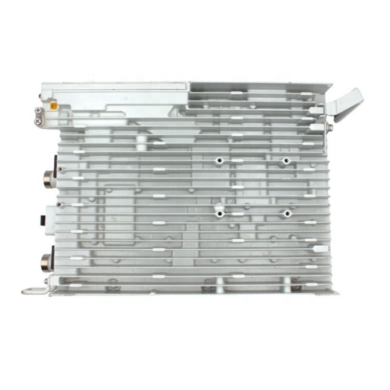
Page 14: Rru Exterior
This section describes the exterior and dimensions of an RRU. Figure 3-1 shows an RRU. Figure 3-1 RRU exterior Figure 3-2 shows RRU dimensions. Figure 3-2 RRU dimensions Issue () Huawei Proprietary and Confidential Copyright © Huawei Technologies Co., Ltd. -
Page 15: Rru Ports
RRU panels. Table 3-1 RRU ports and indicators on the panels Item Silkscreen Description (1) Ports in the cabling RTN(+) Power port cavity NEG(-) CPRI0 Optical/electrical port 0 Issue () Huawei Proprietary and Confidential Copyright © Huawei Technologies Co., Ltd. - Page 16 DBS3900 Optional: ANT_TX/RXB WCDMA and ANT_RXD are used V200R014C00 together. and later versions 1x2T2R ANT_TX/RXA and A single ANT_TX/RXB are used sector together. Issue () Huawei Proprietary and Confidential Copyright © Huawei Technologies Co., Ltd.
- Page 17 DBS3900 WCDMA V200R013C00 Figure 3-5 shows the recommended usage of RF ports on an RRU used for DBS3900 V100R007C00 and later versions, or DBS3900 WCDMA V200R014C00 and later versions. Issue () Huawei Proprietary and Confidential Copyright © Huawei Technologies Co., Ltd.
-
Page 18: Rru Indicators
This section describes six indicators on an RRU. They indicate the running status. For detailed positions of RRU indicators, see 3.2 RRU Ports. Table 3-3 describes RRU indicators. Issue () Huawei Proprietary and Confidential Copyright © Huawei Technologies Co., Ltd. - Page 19 The CPRI link is out of lock because of a for 1s and off for failure in clock lock between two modes or mismatched data rates over CPRI ports. Issue () Huawei Proprietary and Confidential Copyright © Huawei Technologies Co., Ltd.
-
Page 20: Installation Scenarios
3.5.3 Installation Spacing Between RRUs. CAUTION In improper installation scenarios, the heat dissipation efficiency decreases and therefore the RRU may not work properly. Figure 3-6 shows an improper installation scenario. Issue () Huawei Proprietary and Confidential Copyright © Huawei Technologies Co., Ltd. - Page 21 Otherwise, the standard mode is recommended for installing RRUs on the auxiliary pole. Figure 3-7 Requirements for the vertical deviation angle of an RRU (1) RRU (2) Installation support (pole, U-steel, angle steel, or wall) Issue () Huawei Proprietary and Confidential Copyright © Huawei Technologies Co., Ltd.
- Page 22 Figure 3-9 shows a single RRU installed on a pole. Figure 3-9 A single RRU installed on a pole Figure 3-10 shows two RRUs installed on a pole. Issue () Huawei Proprietary and Confidential Copyright © Huawei Technologies Co., Ltd.
- Page 23 Figure 3-10 Two RRUs installed on a pole Figure 3-11, Figure 3-12, and Figure 3-14 show three or more RRUs installed on a pole. Figure 3-11 Three RRUs installed on a pole Issue () Huawei Proprietary and Confidential Copyright © Huawei Technologies Co., Ltd.
- Page 24 RRU3260 Installation Guide 3 Information About the Installation Figure 3-12 Four RRUs installed on a pole Figure 3-13 Four RRUs installed on a pole Issue () Huawei Proprietary and Confidential Copyright © Huawei Technologies Co., Ltd.
- Page 25 3 Information About the Installation Figure 3-14 Six RRUs installed on a pole Figure 3-15 Six RRUs installed on a pole Installing an RRU on U-steel Figure 3-16 shows U-steel specifications. Issue () Huawei Proprietary and Confidential Copyright © Huawei Technologies Co., Ltd.
- Page 26 Figure 3-16 U-steel specifications CAUTION U-steel supports the standard or reverse installation of a single RRU only. Figure 3-17 shows an RRU installed on U-steel. Figure 3-17 RRU installed on U-steel Issue () Huawei Proprietary and Confidential Copyright © Huawei Technologies Co., Ltd.
- Page 27 Figure 3-19 Angle steel specifications CAUTION Angle steel supports the standard or reverse installation of a single RRU only. Figure 3-20 shows an RRU installed on angle steel. Issue () Huawei Proprietary and Confidential Copyright © Huawei Technologies Co., Ltd.
- Page 28 When a single RRU is installed, the wall has a capacity of bearing at least four times the weight of the RRU. Expansion anchor bolts must be tightened to 30 N·m (265.52 lbf·in.) so that the bolts stay secured without damaging the wall. Issue () Huawei Proprietary and Confidential Copyright © Huawei Technologies Co., Ltd.
- Page 29 Figure 3-23 Correct installation of mounting brackets for multiple RRUs installed on an indoor wall in side-mounted mode Figure 3-24 shows an RRU installed on a wall. Issue () Huawei Proprietary and Confidential Copyright © Huawei Technologies Co., Ltd.
- Page 30 RRU. The IFS06 supports a maximum of six RRUs when the ambient temperature is higher than or equal to the lowest operating temperature Issue () Huawei Proprietary and Confidential Copyright © Huawei Technologies Co., Ltd.
- Page 31 IFS06, as shown in Figure 3-26. Figure 3-26 Correct installation of mounting brackets for RRUs installed on an IFS06 Figure 3-27 Figure 3-28 show RRUs installed on an IFS06. Issue () Huawei Proprietary and Confidential Copyright © Huawei Technologies Co., Ltd.
- Page 32 RRU3260 Installation Guide 3 Information About the Installation Figure 3-27 Three RRUs installed on an IFS06 (1) Height-restricted scenario (2) Height-unrestricted scenario Issue () Huawei Proprietary and Confidential Copyright © Huawei Technologies Co., Ltd.
-
Page 33: Installation Clearance Requirements Of An Rru
RRUs and the requirements for the installation spacing between RRUs. 3.5.1 Clearance for a Single RRU This section describes the recommended and minimum clearance for a single RRU. Issue () Huawei Proprietary and Confidential Copyright © Huawei Technologies Co., Ltd. - Page 34 Clearances for a Single RRU in Standard or Reverse Mode Figure 3-29 shows the clearances for a single RRU in standard or reverse mode. Figure 3-29 Clearances for a single RRU in standard or reverse mode Issue () Huawei Proprietary and Confidential Copyright © Huawei Technologies Co., Ltd.
- Page 35 Clearances for a Single Tower-mounted RRU Figure 3-31 Figure 3-32 show the clearances for a single tower-mounted RRU in standard or reverse mode and in side-mounted mode, respectively. Issue () Huawei Proprietary and Confidential Copyright © Huawei Technologies Co., Ltd.
-
Page 36: Clearance For Multiple Rrus
Figure 3-32 Minimum clearance for a single tower-mounted RRU in side-mounted mode 3.5.2 Clearance for Multiple RRUs This section describes the recommended and minimum clearance for multiple RRUs. Issue () Huawei Proprietary and Confidential Copyright © Huawei Technologies Co., Ltd. - Page 37 Figure 3-33 Recommended clearances for three or more RRUs installed on a pole Minimum Clearance for Multiple RRUs Installed in Centralized Mode Figure 3-34 shows the minimum clearance for multiple RRUs installed in centralized mode. Issue () Huawei Proprietary and Confidential Copyright © Huawei Technologies Co., Ltd.
- Page 38 RRUs installed on a wall in standard mode. Figure 3-35 Recommended clearances for three or more RRUs installed on a wall in standard mode Issue () Huawei Proprietary and Confidential Copyright © Huawei Technologies Co., Ltd.
- Page 39 Figure 3-36 Minimum clearances for three or more RRUs installed on a wall in standard mode Recommended Clearance for Multiple RRUs Side-Mounted on a Wall Figure 3-37 shows the recommended clearance for multiple RRUs side-mounted on a wall. Issue () Huawei Proprietary and Confidential Copyright © Huawei Technologies Co., Ltd.
-
Page 40: Installation Spacing Between Rrus
RRUs. Figure 3-38 Recommended horizontal spacing between RRUs Minimum Horizontal Spacing Between RRUs Figure 3-39 shows the minimum horizontal spacing between RRUs. Issue () Huawei Proprietary and Confidential Copyright © Huawei Technologies Co., Ltd. - Page 41 RRUs. Figure 3-40 Recommended vertical spacing between RRUs Minimum Vertical Spacing Between RRUs Figure 3-41 shows the minimum vertical spacing between RRUs. Issue () Huawei Proprietary and Confidential Copyright © Huawei Technologies Co., Ltd.
- Page 42 RRU3260 Installation Guide 3 Information About the Installation Figure 3-41 Minimum vertical spacing between RRUs Issue () Huawei Proprietary and Confidential Copyright © Huawei Technologies Co., Ltd.
-
Page 43: Unpacking The Equipment
The total number does not tally with the Find out the cause and report any missing packing list articles to the local Huawei office. Step 2 Check the exterior of the packing case. Issue () Huawei Proprietary and Confidential... - Page 44 Sign the Packing List with the customer. those on the packing list Either shipment shortage, wrong shipment Report to the local Huawei office. or damaged articles. WARNING To protect the equipment and prevent damage to the equipment, you are advised to keep the...
-
Page 45: Installation Process
The installation process involves installing an RRU and RRU cables, checking the RRU hardware installation, and powering on the RRU. Figure 5-1 shows the process of installing an RRU. Figure 5-1 Process of installing an RRU Issue () Huawei Proprietary and Confidential Copyright © Huawei Technologies Co., Ltd. -
Page 46: Optional) Installing The Plastic Shells Of The Rru
Step 1 Use an M6 Phillips screwdriver to loosen the two screws on the metal sheet of the RRU and remove the metal sheet, as shown in Figure 6-1. Figure 6-1 Removing the metal sheet Issue () Huawei Proprietary and Confidential Copyright © Huawei Technologies Co., Ltd. - Page 47 Step 3 Use four hex screws to secure the plastic shells onto the RRU and use an M6 hex key wrench to tighten the screws to 2.8 N•m (24.78 lbf•in.), as shown in Figure 6-3. Issue () Huawei Proprietary and Confidential Copyright © Huawei Technologies Co., Ltd.
- Page 48 RRU3260 Installation Guide 6 (Optional) Installing the Plastic Shells of the RRU Figure 6-3 Installing the plastic shells of the RRU ----End Issue () Huawei Proprietary and Confidential Copyright © Huawei Technologies Co., Ltd.
-
Page 49: Hoisting An Rru And Related Cables Onto A Tower
7.3 Hoisting Power Cables onto a Tower This section describes the procedure for hoisting power cables onto a tower and the precautions that must be taken. Issue () Huawei Proprietary and Confidential Copyright © Huawei Technologies Co., Ltd. -
Page 50: Hoisting An Rru Onto A Tower
Hoist mounting kits onto the tower and then install the mounting kits before hoisting the RRU onto the tower. When hoisting the mounting kits and RRU, protect them from colliding with the tower. Issue () Huawei Proprietary and Confidential Copyright © Huawei Technologies Co., Ltd. - Page 51 Installation engineer C binds the RRU mounting kits properly using a lifting sling, as shown Figure 7-2, and binds the RRU using a lifting sling and a traction sling, as shown in Figure 7-3. Issue () Huawei Proprietary and Confidential Copyright © Huawei Technologies Co., Ltd.
- Page 52 7 Hoisting an RRU and Related Cables onto a Tower Figure 7-2 Binding mounting kits for the RRU Figure 7-3 Binding the RRU (1) Handle (2) Lifting sling (3) Traction eye (4) Traction sling Issue () Huawei Proprietary and Confidential Copyright © Huawei Technologies Co., Ltd.
- Page 53 Do not hoist any thing by the traction eye. l Do not hoist the RRU by the handle or traction eye only, as shown in Figure 7-4 Figure 7-5. Figure 7-4 Incorrect binding method Issue () Huawei Proprietary and Confidential Copyright © Huawei Technologies Co., Ltd.
-
Page 54: Hoisting Fiber Optic Cables Onto A Tower
Cabling requirements for power cables are met. For details, see 9.1 Cabling Requirements. Procedure Step 1 Hoist the fiber optic cables onto the tower, as shown in Figure 7-6. Issue () Huawei Proprietary and Confidential Copyright © Huawei Technologies Co., Ltd. - Page 55 4 m (13.12 ft) away from the lifting sling, as shown in Figure 7-7. Issue () Huawei Proprietary and Confidential Copyright © Huawei Technologies Co., Ltd.
- Page 56 Installation engineer B rotates the fiber spools at the speed of 5 m (16.4 ft) to 15 m (49.21 ft) per minute to coil the fiber optic cables. Issue () Huawei Proprietary and Confidential Copyright © Huawei Technologies Co., Ltd.
-
Page 57: Hoisting Power Cables Onto A Tower
The procedure for adding a connector to the RRU power cable on the RRU side is done under the tower. Procedure Step 1 Hoist the power cables onto the tower, as shown in Figure 7-9. Issue () Huawei Proprietary and Confidential Copyright © Huawei Technologies Co., Ltd. - Page 58 Figure 7-10. NOTE The connector on the power cable in the figure is only an example. The actual connector may vary according to the situation. Issue () Huawei Proprietary and Confidential Copyright © Huawei Technologies Co., Ltd.
- Page 59 Wrap the PVC insulation tape from 30 mm (1.18 in.) away from one end of the connector until it reaches the other end of the connector. The total length of the wrapped connector is 100 mm (3.94 in.). Issue () Huawei Proprietary and Confidential Copyright © Huawei Technologies Co., Ltd.
- Page 60 Step 3 Remove the cable ties, PVC insulation tape, and lifting sling. NOTE The procedure for hoisting the power cables onto the tower is for your reference only. ----End Issue () Huawei Proprietary and Confidential Copyright © Huawei Technologies Co., Ltd.
-
Page 61: Installing The Rru
This section describes the procedure and precautions for installing the RRU on a wall. 8.6 Installing an RRU on an IFS06 This section describes the procedure and precautions for installing an RRU on an IFS06. Issue () Huawei Proprietary and Confidential Copyright © Huawei Technologies Co., Ltd. -
Page 62: Mounting Kits For An Rru
Figure 8-2 12 L blade RRU mounting kit (1) Main bracket (2) Pole installation (3) Auxiliary bracket (4) Nut (5) Square-neck (6) Hoist clamp on bracket bolt the main bracket Issue () Huawei Proprietary and Confidential Copyright © Huawei Technologies Co., Ltd. -
Page 63: Installing The Rru On A Pole
If the pole must be installed on the ground, determine a position for installing the mounting brackets according to Figure 8-3. Figure 8-3 Distance between the mounting brackets and the ground Issue () Huawei Proprietary and Confidential Copyright © Huawei Technologies Co., Ltd. - Page 64 Tighten the nuts on the two square-neck bolts alternatively. After the main and auxiliary brackets are secured properly, measure the spacing between the brackets on both sides and ensure that the spacing is the same on the two sides. Issue () Huawei Proprietary and Confidential Copyright © Huawei Technologies Co., Ltd.
- Page 65 5 N·m (44.25 lbf·in.) so that the attachment plate and main bracket are firmly secured, as shown in Figure 8-7. Issue () Huawei Proprietary and Confidential Copyright © Huawei Technologies Co., Ltd.
-
Page 66: Installing Two Rrus
Place a foam pad or cardboard under the RRU to protect the RRU housing from damage during the installation. Procedure Step 1 Install the first RRU onto the main bracket, as shown in Figure 8-8. For details, see 8.2.1 Installing a Single RRU. Issue () Huawei Proprietary and Confidential Copyright © Huawei Technologies Co., Ltd. - Page 67 Figure 8-9 Removing the RRU main bracket (1) Main bracket (2) Pole installation bracket Step 3 Install the removed main bracket on one side of the first main bracket, as shown in Figure 8-10. Issue () Huawei Proprietary and Confidential Copyright © Huawei Technologies Co., Ltd.
- Page 68 (1) Removed main bracket Step 4 Install the second RRU onto the main bracket, as shown in Figure 8-11. Figure 8-11 Installing the second RRU onto the main bracket Issue () Huawei Proprietary and Confidential Copyright © Huawei Technologies Co., Ltd.
- Page 69 Figure 8-12. Figure 8-12 Securing the captive screw into the connection hole Step 5 Install the metal sheet for neighboring RRUs, as shown in Figure 8-13. Issue () Huawei Proprietary and Confidential Copyright © Huawei Technologies Co., Ltd.
-
Page 70: Installing Three Or More Rrus
Do not stand the RRU upright because the RF ports cannot support the weight of the RRU. l Place a foam pad or cardboard under the RRU to protect the RRU housing from damage during the installation. Issue () Huawei Proprietary and Confidential Copyright © Huawei Technologies Co., Ltd. - Page 71 Step 2 Use an M6 inner hexagon screwdriver to remove the four inner hexagon screws from the second set of mounting brackets, and remove the main bracket from the auxiliary bracket, as shown in Figure 8-15. Issue () Huawei Proprietary and Confidential Copyright © Huawei Technologies Co., Ltd.
- Page 72 RRU, with a torque of 5 N·m (44.25 lbf·in.), as shown in Figure 8-16. CAUTION The third main bracket must be installed with the opening ends of U-shaped slots on both sides facing downwards. Issue () Huawei Proprietary and Confidential Copyright © Huawei Technologies Co., Ltd.
- Page 73 (2) Metal sheet Use an M6 Phillips screwdriver to loosen the screw on the metal sheet farther from the handle of the first RRU and remove the screw. Issue () Huawei Proprietary and Confidential Copyright © Huawei Technologies Co., Ltd.
- Page 74 5 N·m (44.25 lbf·in.) so that the attachment plate and main bracket are firmly secured, as shown in Figure 8-19. Issue () Huawei Proprietary and Confidential Copyright © Huawei Technologies Co., Ltd.
-
Page 75: Installing The Rru On U-Steel
Do not stand the RRU upright because the RF ports cannot support the weight of the RRU. l Place a foam pad or cardboard under the RRU to protect the RRU housing from damage during the installation. Issue () Huawei Proprietary and Confidential Copyright © Huawei Technologies Co., Ltd. - Page 76 3.5.1 Clearance for a Single RRU to determine a position. If the RRU must be installed on U-steel secured on the ground, see Figure 8-21 to determine a position. Issue () Huawei Proprietary and Confidential Copyright © Huawei Technologies Co., Ltd.
- Page 77 Adjust the position of the nut and remove one end of the square-neck bolt from the slot on the auxiliary bracket. Slide the mounting brackets onto the U-steel horizontally and insert the square-neck bolt into the slot. Issue () Huawei Proprietary and Confidential Copyright © Huawei Technologies Co., Ltd.
- Page 78 Step 4 Use an inner hexagon screwdriver to remove the attachment plate from one side of the RRU, reinstall the attachment plate onto the rear of the RRU, and tighten the four stainless screws to 5 N·m (44.25 lbf·in.), as shown in Figure 8-24. Issue () Huawei Proprietary and Confidential Copyright © Huawei Technologies Co., Ltd.
- Page 79 Step 6 Use an inner hexagon screwdriver to tighten the captive screw into the holes on the top of the attachment plate and main bracket to 5 N·m (44.25 lbf·in.) so that the attachment plate and main bracket are firmly secured, as shown in Figure 8-26. Issue () Huawei Proprietary and Confidential Copyright © Huawei Technologies Co., Ltd.
-
Page 80: Installing The Rru On Angle Steel
Place a foam pad or cardboard under the RRU to protect the RRU housing from damage during the installation. Context Figure 8-27 shows the top view of the RRU installed on angle steel. Issue () Huawei Proprietary and Confidential Copyright © Huawei Technologies Co., Ltd. - Page 81 It is recommended that the mounting brackets be installed at a height of 1200 mm (47.24 in.) to 1600 mm (62.99 in.) above the ground. Step 2 Install the RRU mounting brackets, as shown in Figure 8-29. Issue () Huawei Proprietary and Confidential Copyright © Huawei Technologies Co., Ltd.
- Page 82 Tighten the nuts on the two square-neck bolts alternatively. After the main and auxiliary brackets are secured properly, measure the spacing between the brackets on both sides and ensure that the spacing is the same on the two sides. Issue () Huawei Proprietary and Confidential Copyright © Huawei Technologies Co., Ltd.
- Page 83 Figure 8-31. Figure 8-31 Installing the attachment plate onto the rear of the RRU Step 5 Install the RRU onto the main bracket, as shown in Figure 8-32. Issue () Huawei Proprietary and Confidential Copyright © Huawei Technologies Co., Ltd.
- Page 84 5 N·m (44.25 lbf·in.) so that the attachment plate and main bracket are firmly secured, as shown in Figure 8-33. Figure 8-33 Securing the captive screw into the connection hole ----End Issue () Huawei Proprietary and Confidential Copyright © Huawei Technologies Co., Ltd.
-
Page 85: Installing The Rru On A Wall
Expansion anchor bolts must be tightened to 30 N·m (265.52 lbf·in.) so that the bolts stay secured without damaging the wall. Procedure Step 1 Disassemble the RRU mounting brackets, as shown in Figure 8-34. Issue () Huawei Proprietary and Confidential Copyright © Huawei Technologies Co., Ltd. - Page 86 Step 2 Place the pole installation bracket against the installation position, use a level to verify that the pole installation bracket is placed horizontally, and then mark anchor points with a marker, as shown in Figure 8-35. Issue () Huawei Proprietary and Confidential Copyright © Huawei Technologies Co., Ltd.
- Page 87 Step 3 Drill holes at the anchor points, and then insert expansion anchor bolt assemblies, as shown in Figure 8-36. Figure 8-36 Drilling a hole and inserting expansion anchor bolt assemblies (1) M10x80 bolt (2) Nut (3) Spring washer (4) Flat washer (5) Expansion tube Issue () Huawei Proprietary and Confidential Copyright © Huawei Technologies Co., Ltd.
- Page 88 30 N·m (265.52 lbf·in.), as shown in Figure 8-37. Figure 8-37 Installing the pole installation bracket on the expansion anchor bolts Issue () Huawei Proprietary and Confidential Copyright © Huawei Technologies Co., Ltd.
- Page 89 Step 6 Use an inner hexagon screwdriver to remove the attachment plate from one side of the RRU, reinstall the attachment plate onto the rear of the RRU, and tighten the four stainless screws to 5 N·m (44.25 lbf·in.), as shown in Figure 8-39. Issue () Huawei Proprietary and Confidential Copyright © Huawei Technologies Co., Ltd.
- Page 90 Step 8 Use an inner hexagon screwdriver to tighten the captive screw into the holes on the top of the attachment plate and main bracket to 5 N·m (44.25 lbf·in.) so that the attachment plate and main bracket are firmly secured, as shown in Figure 8-41. Issue () Huawei Proprietary and Confidential Copyright © Huawei Technologies Co., Ltd.
-
Page 91: Installing An Rru On An Ifs06
RRUs. When the ambient temperature is higher than or equal to the lowest working temperature of the RRU and at least 10°C (50°F) lower than the highest working temperature of the RRU, the IFS06 supports a maximum of six RRUs. Issue () Huawei Proprietary and Confidential Copyright © Huawei Technologies Co., Ltd. - Page 92 Step 2 Use the M10x50 bolts delivered with the IFS06 to secure the pole installation bracket to the IFS06, and then use an M10 torque socket wrench to secure the bolts to 30 N·m (265.52 lbf·in.). Issue () Huawei Proprietary and Confidential Copyright © Huawei Technologies Co., Ltd.
- Page 93 Figure 8-43 Installing the pole installation bracket in height-restricted scenarios (1) Spring washer (2) Rubber washer Height-unrestricted scenarios Install the pole installation bracket, as shown in Figure 8-44. Issue () Huawei Proprietary and Confidential Copyright © Huawei Technologies Co., Ltd.
- Page 94 Step 3 Attach the main bracket to the pole installation bracket, and use an inner hexagon screwdriver to tighten four M6x16 screws to 5 N·m (44.25 lbf·in.) so that the main bracket and pole installation bracket are firmly secured, as shown in Figure 8-45. Issue () Huawei Proprietary and Confidential Copyright © Huawei Technologies Co., Ltd.
- Page 95 5 N·m (44.25 lbf·in.) so that the attachment plate and main bracket are firmly secured, as shown in Figure 8-46. Issue () Huawei Proprietary and Confidential Copyright © Huawei Technologies Co., Ltd.
- Page 96 8 Installing the RRU Figure 8-46 Installing the RRU onto the main bracket Step 5 Install the RRUs on the lower level from left to right, as shown in Figure 8-47. Issue () Huawei Proprietary and Confidential Copyright © Huawei Technologies Co., Ltd.
- Page 97 RRU and at least 10°C (10°F) lower than the highest operating temperature of the RRU, repeat the preceding steps to install the RRUs on the higher level, as shown in Figure 8-48. Issue () Huawei Proprietary and Confidential Copyright © Huawei Technologies Co., Ltd.
- Page 98 RRU3260 Installation Guide 8 Installing the RRU Figure 8-48 Installing RRUs on the higher level ----End Issue () Huawei Proprietary and Confidential Copyright © Huawei Technologies Co., Ltd.
-
Page 99: Installing Rru Cables
9.11 Installing a CPRI Fiber Optic Cable This section describes the procedure for installing a CPRI fiber optic cable. 9.12 Closing the Cover Plate of an RRU Cabling Cavity Issue () Huawei Proprietary and Confidential Copyright © Huawei Technologies Co., Ltd. - Page 100 RRU3260 Installation Guide 9 Installing RRU Cables This section describes the procedure for closing the cover plate of an RRU cabling cavity. Issue () Huawei Proprietary and Confidential Copyright © Huawei Technologies Co., Ltd.
-
Page 101: Cabling Requirements
Sufficient slack (recommended for about 0.1 m [0.33 ft]) is provided in cables at turns or the position close to a device, facilitating cable and device maintenance. Indoor Cabling Requirements Cables are routed indoors through the feeder window. Issue () Huawei Proprietary and Confidential Copyright © Huawei Technologies Co., Ltd. - Page 102 After routing cables neatly and correctly, tighten the screws on cable clips. Secure cables on the cable tray, as shown in Figure 9-1. Figure 9-1 Securing cables on the cable tray Issue () Huawei Proprietary and Confidential Copyright © Huawei Technologies Co., Ltd.
- Page 103 Cables must be routed by only qualified and trained personnel before all preparations are made. Cables are routed in an untangled and orderly fashion. Issue () Huawei Proprietary and Confidential Copyright © Huawei Technologies Co., Ltd.
- Page 104 Figure 9-3 E1 cables routed through the cabinet Cabling Requirements for Fiber Optic Cables Fiber optic cables must be routed by at least three qualified and trained personnel before all preparations are made. Issue () Huawei Proprietary and Confidential Copyright © Huawei Technologies Co., Ltd.
- Page 105 Figure 9-4, Figure 9-5 Figure 9-6. Figure 9-4 CPRI fiber optic cables routed through the cabinet (1) Figure 9-5 CPRI fiber optic cables routed through the cabinet (2) Issue () Huawei Proprietary and Confidential Copyright © Huawei Technologies Co., Ltd.
-
Page 106: Cable Connections
A lower-level RRU obtains power directly from the external power system, but not from an upper- level RRU using a power cable. Figure 9-7 shows the cable connections for a single RRU. Issue () Huawei Proprietary and Confidential Copyright © Huawei Technologies Co., Ltd. - Page 107 (3) RRU AISG multi-wire cable (4) RRU AISG extension cable (5) RRU power cable (6) CPRI fiber optic cable (7) RRU alarm cable Figure 9-8 shows the cable connections for multiple RRUs. Issue () Huawei Proprietary and Confidential Copyright © Huawei Technologies Co., Ltd.
-
Page 108: Installation Process
(3) RRU power cable (4) CPRI fiber optic cable 9.3 Installation Process This section describes the process of installing RRU cables. Figure 9-9 shows the process of installing RRU cables. Issue () Huawei Proprietary and Confidential Copyright © Huawei Technologies Co., Ltd. -
Page 109: Rru Cable List
RRU PGND OT terminal (16 Ground OT terminal (16 Ground terminal Cable terminal on the on the ground bar or 0.025 in. or 0.025 in. , M6) , M8) Issue () Huawei Proprietary and Confidential Copyright © Huawei Technologies Co., Ltd. - Page 110 RRU AISG RET port on Standard AISG Standard AISG Multi-Wire waterproofed the RRU female connector male connector Cable male connector on the RCU or on the AISG extension cable Issue () Huawei Proprietary and Confidential Copyright © Huawei Technologies Co., Ltd.
-
Page 111: Installing An Rru Pgnd Cable
Connect the M6 OT terminal at one end of the PGND cable to the ground terminal at the RRU bottom and the M8 OT terminal at the other end to the external ground bar, as shown in Figure 9-10. Figure 9-10 Installing an RRU PGND cable Issue () Huawei Proprietary and Confidential Copyright © Huawei Technologies Co., Ltd. -
Page 112: Installing An Rru Rf Jumper
Step 1 Connect the DIN male connector at one end of the RRU RF jumper to the ANT port on the RRU, and use a torque wrench to tighten the connector to 25 N·m (221.27 lbf·in.), as shown in Figure 9-12. Figure 9-12 Installing an RRU RF jumper Issue () Huawei Proprietary and Confidential Copyright © Huawei Technologies Co., Ltd. - Page 113 Wrap three layers of waterproof tape on the connector, first from bottom up, then from top down, and finally from bottom up. Start wrapping the connector at a position 50 mm (1.97 Issue () Huawei Proprietary and Confidential Copyright © Huawei Technologies Co., Ltd.
- Page 114 Wrap each connector with three layers of waterproof tape, from bottom up, then from top down, and finally from bottom up. Do not cut the tape Issue () Huawei Proprietary and Confidential Copyright © Huawei Technologies Co., Ltd.
-
Page 115: Installing An Rru Aisg Multi-Wire Cable And Aisg Extension Cable
Link the waterproofed DB9 connector at one end the AISG multi-wire cable to the RET port on the RRU bottom, as shown in Figure 9-15. Issue () Huawei Proprietary and Confidential Copyright © Huawei Technologies Co., Ltd. - Page 116 Link the waterproofed DB9 connector at one end of the AISG multi-wire cable to the RET port on the RRU bottom, and link the other end to the standard AISG male connector of the AISG extension cable, as shown in Figure 9-16. Issue () Huawei Proprietary and Confidential Copyright © Huawei Technologies Co., Ltd.
- Page 117 Connect the other end of the AISG extension cable to the standard AISG male connector on the RCU, as shown in Figure 9-17. Figure 9-17 Installing an RRU AISG extension cable Issue () Huawei Proprietary and Confidential Copyright © Huawei Technologies Co., Ltd.
-
Page 118: Installing An Rru Alarm Cable
0.4 N·m (3.54 lbf·in.). Step 4 Route the cables according to the instructions in 9.1 Cabling Requirements, and then use cable ties to bind the cables. Issue () Huawei Proprietary and Confidential Copyright © Huawei Technologies Co., Ltd. -
Page 119: Opening The Cover Plate Of An Rru Cabling Cavity
(4) Cable trough for the power cable (5) Waterproof block (6) Cable trough for the fiber optic cable Step 3 Loosen the screws on the clip, and open the clip, as shown Figure 9-20. Issue () Huawei Proprietary and Confidential Copyright © Huawei Technologies Co., Ltd. -
Page 120: Installing An Rru Power Cable
) (12 AWG) and 5.3 mm (0.0082 in. ) (10 AWG) complying with North American standards, 4 mm (0.006 in. ) and 6 mm (0.0093 in. ) complying with European standards. Issue () Huawei Proprietary and Confidential Copyright © Huawei Technologies Co., Ltd. - Page 121 Step 1 Connect the tool-less female connector (pressfit type) at one end of the RRU power cable to the power supply socket on the RRU, as shown in Figure 9-21. Issue () Huawei Proprietary and Confidential Copyright © Huawei Technologies Co., Ltd.
-
Page 122: Installing A Cpri Fiber Optic Cable
Step 4 Label the installed cables according to the instructions in Attaching a Cable-Tying Label. ----End 9.11 Installing a CPRI Fiber Optic Cable This section describes the procedure for installing a CPRI fiber optic cable. Issue () Huawei Proprietary and Confidential Copyright © Huawei Technologies Co., Ltd. - Page 123 20 minutes. Step 2 Connect the end labeled 1A and 1B of the fiber optic cable to the optical module on the RRU side, as shown in Figure 9-23. Issue () Huawei Proprietary and Confidential Copyright © Huawei Technologies Co., Ltd.
-
Page 124: Closing The Cover Plate Of An Rru Cabling Cavity
Step 5 Label the installed cables according to the instructions in Attaching an L-Shaped Label. ----End 9.12 Closing the Cover Plate of an RRU Cabling Cavity This section describes the procedure for closing the cover plate of an RRU cabling cavity. Issue () Huawei Proprietary and Confidential Copyright © Huawei Technologies Co., Ltd. - Page 125 Step 2 Insert waterproof blocks into vacant cable troughs in the cabling cavity, as shown in Figure 9-25. CAUTION Ensure that cables and waterproof blocks are properly inserted into troughs. Issue () Huawei Proprietary and Confidential Copyright © Huawei Technologies Co., Ltd.
- Page 126 Figure 9-26. Then tighten the screws to 2 N·m (17.7 lbf·in.) in the same sequence. Figure 9-26 Closing the cover plate of an RRU cabling cavity Issue () Huawei Proprietary and Confidential Copyright © Huawei Technologies Co., Ltd.
- Page 127 RRU3260 Installation Guide 9 Installing RRU Cables Step 4 Take off the ESD gloves, and pack up all the tools. ----End Issue () Huawei Proprietary and Confidential Copyright © Huawei Technologies Co., Ltd.
-
Page 128: Checking The Rru Hardware Installation
The connectors of each signal cable are intact and securely linked, and these cables are not damaged or broken. Labels are correct, legible, and complete at both ends of each cable, feeder, and jumper. Issue () Huawei Proprietary and Confidential Copyright © Huawei Technologies Co., Ltd. -
Page 129: Powering On An Rru
For details about how to power on an RRU, see Powering On an RRU. For details about how to power off an RRU, see section "Powering-Off the RRU" in RRU Maintenance Guide. Issue () Huawei Proprietary and Confidential Copyright © Huawei Technologies Co., Ltd. - Page 130 -36 V DC to -57 V DC. (b) The RUN indicator on the RRU is on for 1s and off for 1s. The ALM indicator is steady off. Issue () Huawei Proprietary and Confidential Copyright © Huawei Technologies Co., Ltd.
-
Page 131: Appendix
12.1 Adding a Tool-Less Female Connector (Pressfit Type) to the RRU Power Cable on the RRU Side This section describes the procedure for adding a tool-less female connector (pressfit type) to the RRU power cable on the RRU side. Issue () Huawei Proprietary and Confidential Copyright © Huawei Technologies Co., Ltd. -
Page 132: Adding A Tool-Less Female Connector (Pressfit Type) To The Rru Power Cable On The Rru Side
Step 1 Determine the length of the power cable for different operations based on the labels, as shown Figure 12-2. Figure 12-2 Determining the length of the power cable Issue () Huawei Proprietary and Confidential Copyright © Huawei Technologies Co., Ltd. - Page 133 Figure 12-5 Matched length Step 4 Add a tool-less female connector (pressfit type) to two core wires. Tighten the screws using a Phillips screwdriver, as shown in Figure 12-6. Issue () Huawei Proprietary and Confidential Copyright © Huawei Technologies Co., Ltd.
- Page 134 Step 5 Strip the specified length of the sheath off the power cable to expose the intact shield layer, as shown in Figure 12-8. Figure 12-8 Stripping the sheath off the power cable Issue () Huawei Proprietary and Confidential Copyright © Huawei Technologies Co., Ltd.
- Page 135 Each core wire is exposed outside the tool-less female connector (pressfit type) for 1.5 mm (0.059 [in.]), as shown in Figure 12-9. Figure 12-9 Inserting core wires into the tool-less female connector (pressfit type) ----End Issue () Huawei Proprietary and Confidential Copyright © Huawei Technologies Co., Ltd.
Need help?
Do you have a question about the DBS3900 LTE and is the answer not in the manual?
Questions and answers