Table of Contents
Advertisement
Quick Links
INSTALLATION
MANUAL
R32 Split Series
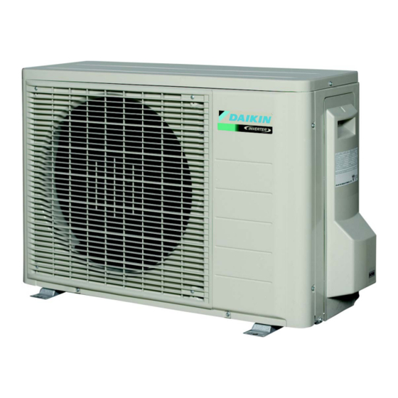
Models
RXJ20LV1B
RXJ25LV1B
RXJ35LV1B
RXM20LV1B
RXM25LV1B
RXM35LV1B
Installation manual
Installationsanleitung
Split-Baureihe R32
Manuel d'installation
Montagehandleiding
R32 Split-systeem
Manual de instalación
Manuale d'installazione
Serie Multiambienti R32
Εγχειρίδιο εγκατάστασης
∆ιαιρούμενης σειράς R32
Manual de Instalação
Руководство по монтажу
Серия R32 с раздельной установкой
English
R32 Split series
Deutsch
Français
Série split R32
Nederlands
Español
Serie Split R32
Italiano
Ελληνικά
Portugues
Série split R32
Русский
Montaj kılavuzları
Türkçe
R32 Split serisi
Advertisement
Table of Contents

Summary of Contents for Daikin RXJ20LV1B
- Page 1 R32 Split series Installationsanleitung Deutsch Split-Baureihe R32 Manuel d’installation Français Série split R32 Montagehandleiding Nederlands R32 Split-systeem Models Manual de instalación RXJ20LV1B Español Serie Split R32 RXJ25LV1B Manuale d’installazione RXJ35LV1B Italiano Serie Multiambienti R32 RXM20LV1B RXM25LV1B Εγχειρίδιο εγκατάστασης Ελληνικά ∆ιαιρούμενης σειράς R32 RXM35LV1B Manual de Instalação...
- Page 2 3P389789-3...
-
Page 3: Safety Precautions
Safety Precautions Read the precautions in this manual This appliance is filled with R32. carefully before operating the unit. • The precautions described herein are classified as WARNING and CAUTION. They both contain important information regarding safety. Be sure to observe all precautions without fail. •... -
Page 4: Precautions For Selecting The Location
Safety Precautions CAUTION • Do not install the air conditioner at any place where there is a danger of flammable gas leakage. In the event of a gas leakage, build-up of gas near the air conditioner may cause a fire to break out. •... - Page 5 Precautions for Selecting the Location CAUTION When operating the air conditioner in a low outdoor ambient temperature, be sure to follow the instructions described below. ● Construct a large canopy • To prevent exposure to wind, install the outdoor unit with its suction ●...
-
Page 6: Outdoor Unit Installation Drawings
Outdoor Unit Installation Drawings Max. allowable piping length Min. allowable piping length 1.5m Max. allowable piping height Wrap the insulation pipe with Additional refrigerant the finishing tape from bottom required for refrigerant pipe 20g/m to top. exceeding 10m in length. Gas pipe O.D. -
Page 7: Precautions On Installation
Installation Guidelines • Where a wall or other obstacle is in the path of outdoor unit’s inlet or outlet airflow, follow the installation guidelines below. • For any of the following installation patterns, the wall height on the outlet side should be 1200mm or less. Wall facing one side Wall facing two sides More than 100... - Page 8 Outdoor Unit Installation Flaring the pipe end 1) Cut the pipe end with a pipe cutter. (Cut exactly at right angles.) Remove burrs. 2) Remove burrs with the cut surface facing downward so that the chips do not enter the pipe. Flaring Set exactly at the position shown below.
- Page 9 Outdoor Unit Installation 4-1 Cautions on pipe handling Wall 1) Protect the open end of the pipe against dust and moisture. Be sure to place a cap. 2) All pipe bends should be as gentle as possible. Use a pipe bender Rain If no flare cap is for bending.
- Page 10 Outdoor Unit Installation 6) Turn the liquid stop valve’s rod 90 degrees counterclockwise with a hexagonal wrench to open valve. Close it after 5 seconds, and check for gas leakage. Using soapy water, check for gas leakage from indoor unit’s flare and outdoor unit’s flare and valve rods. After the check is complete, wipe all soapy water off.
-
Page 11: Pump Down Operation
Pump Down Operation In order to protect the environment, be sure to pump down when relocating or disposing of the unit. 1) Remove the valve cap from liquid stop valve and gas stop valve. Hexagonal 2) Carry out forced cooling operation. wrench 3) After 5 to 10 minutes, close the liquid stop valve with a hexagonal wrench. - Page 12 Wiring WARNING • Do not use tapped wires, stranded wires, extension cords, or starburst connections, as they may cause overheating, electrical shock, or fire. • Do not use locally purchased electrical parts inside the product. (Do not branch the power for the drain pump, etc., from the terminal block.) Doing so may cause electric shock or fire.
- Page 13 Wiring Wiring diagram Terminal strip Field wiring Connector Relay connector Connection Terminal Black Orange Blue Brown White Green Yellow Grey Notes Refer to the nameplate of the unit for power requirements. TO INDOOR UNIT To indoor unit POWER SUPPLY Power supply IN CASE OF COOLING ONLY TYPE In case of cooling only type OUTDOOR...
-
Page 14: Trial Operation And Testing
Trial Operation and Testing Trial operation and testing 1-1 Measure the supply voltage and make sure that it falls in the specified range. 1-2 Trial operation should be carried out in either cooling or heating mode. • In cooling mode, select the lowest programmable temperature; in heating mode, select the highest programmable temperature. - Page 16 3P386697-1B 2014.10...


Need help?
Do you have a question about the RXJ20LV1B and is the answer not in the manual?
Questions and answers