Sign In
Upload
Download
Table of Contents
Contents
Add to my manuals
Delete from my manuals
Share
URL of this page:
HTML Link:
Bookmark this page
Add
Manual will be automatically added to "My Manuals"
Print this page
×
Bookmark added
×
Added to my manuals
Manuals
Brands
Daikin Manuals
Air Conditioner
RXA20A2V1B
Installation manual
Daikin RXA20A2V1B Installation Manual
R32 split series
Hide thumbs
Also See for RXA20A2V1B
:
Service manual
(76 pages)
1
2
Table Of Contents
3
4
5
6
7
8
9
10
11
12
13
14
15
16
page
of
16
Go
/
16
Contents
Table of Contents
Troubleshooting
Bookmarks
Table of Contents
1 About the Documentation
2 About the Box
Table of Contents
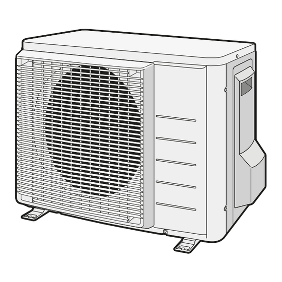
Outdoor Unit
To Remove the Accessories from the Outdoor Unit
About this Document
3 Preparation
Preparing the Installation Site
Installation Site Requirements of the Outdoor Unit
Additional Installation Site Requirements of the Outdoor Unit in Cold Climates
Preparing Refrigerant Piping
Refrigerant Piping Requirements
Refrigerant Piping Length and Height Difference
Refrigerant Piping Insulation
4 Installation
Mounting the Outdoor Unit
To Provide the Installation Structure
To Install the Outdoor Unit
To Provide Drainage
To Prevent the Outdoor Unit from Falling over
Connecting the Refrigerant Piping
Guidelines When Connecting the Refrigerant Piping
Using the Stop Valve and Service Port
To Connect the Refrigerant Piping to the Outdoor Unit
Checking the Refrigerant Piping
To Check for Leaks
To Perform Vacuum Drying
Charging Refrigerant
About Charging Refrigerant
About the Refrigerant
To Determine the Additional Refrigerant Amount
To Determine the Complete Recharge Amount
To Charge Additional Refrigerant
To Fix the Fluorinated Greenhouse Gases Label
Connecting the Electrical Wiring
Guidelines When Connecting the Electrical Wiring
Specifications of Standard Wiring Components
To Connect the Electrical Wiring on the Outdoor Unit
Finishing the Outdoor Unit Installation
To Finish the Outdoor Unit Installation
About the Compressor
5 Commissioning
Checklist before Commissioning
Checklist During Commissioning
To Perform a Test Run
6 Configuration
To Set the Facility Mode
7 Troubleshooting
Fault Diagnosis Using LED on Outdoor Unit PCB
8 Disposal
To Pump down
To Start and Stop Forced Cooling
To Start/Stop Forced Cooling Using the Indoor Unit ON/OFF Switch
To Start/Stop Forced Cooling Using the Indoor Unit User Interface
9 Technical Data
Wiring Diagram
Advertisement
Quick Links
1
Wiring Diagram
Download this manual
Installation manual
R32 split series
RXA20A2V1B
Installation manual
RXA25A2V1B
English
R32 split series
RXA35A2V1B
Table of
Contents
Previous
Page
Next
Page
1
2
3
4
5
Advertisement
Table of Contents
Need help?
Do you have a question about the RXA20A2V1B and is the answer not in the manual?
Ask a question
Questions and answers
Related Manuals for Daikin RXA20A2V1B
Air Conditioner Daikin Stylish Series Service Manual
Split stylish r32 (76 pages)
Air Conditioner Daikin RXA42A2V1B Installation Manual
R32 split series (16 pages)
Air Conditioner Daikin RXF60B2V1B Installer's Reference Manual
R32 split series (28 pages)
Air Conditioner Daikin R32 Split Series Installation Manual
(16 pages)
Air Conditioner Daikin R32 split Series Installer's Reference Manual
(68 pages)
Air Conditioner Daikin R32 Split Series Installer's Reference Manual
(76 pages)
Air Conditioner Daikin RXF71A2V1B Installation Manual
(28 pages)
Air Conditioner Daikin Stylish Series Service Manual
Split r32 (168 pages)
Air Conditioner Daikin FTXA20A Service Manual
Split stylish r32 (192 pages)
Air Conditioner Daikin FTXA50BB Installation Manual
(16 pages)
Air Conditioner Daikin RXA25A5V1B8 Installation Manual
R32 split system air conditioners (16 pages)
Air Conditioner Daikin RXA35A5V1B8 Installation Manual
R32 split system air conditioners (16 pages)
Air Conditioner Daikin RXA-A8 Installation Manual
R32 split system air conditioners (16 pages)
Air Conditioner Daikin RXA42B5V1B8 Installer's Reference Manual
(80 pages)
Air Conditioner Daikin RXA25A5V1B Installer's Reference Manual
R32 split system air conditioners (68 pages)
Air Conditioner Daikin RXA35A5V1B Installer's Reference Manual
R32 split system air conditioners (68 pages)
This manual is also suitable for:
Rxa25a2v1b
Rxa35a2v1b
Rxj25m9
Rxa-a
Table of Contents
Print
Rename the bookmark
Delete bookmark?
Delete from my manuals?
Login
Sign In
OR
Sign in with Facebook
Sign in with Google
Upload manual
Upload from disk
Upload from URL


Need help?
Do you have a question about the RXA20A2V1B and is the answer not in the manual?
Questions and answers