Advertisement
Quick Links
101 N. Alloy Dr.
Fenton, MI 48430
Research, Development and Manufacturing of Precision Measuring Systems
LMI 241 or LMI 241-B to the LMI 440 or ASI DataMyte 501
This instruction will outline:
I.
GAGE CONFIGURATION .........................................................................................................2
Flush Condition.........................................................................................................................2
Gap Condition ...........................................................................................................................6
II. MASTERING INSTRUCTIONS .................................................................................................9
III. Verification of the Mastering .....................................................................................................11
Flush Verification ...................................................................................................................11
Gap Verification......................................................................................................................12
Form: CA 030
1-4-05
CONFIGURATION and MASTERING for the
1
R:\Quality\Calibration Instructions\CA 030.docR:\Quality\Calibration Instructions\CA
030.doc
2
3
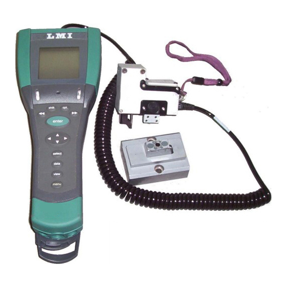
Required Equipment:
1
LMI 440 or ASIDataMyte 501
2
LMI 241 or 241-B transducer
3
LMI 720 master block
4
LMI 6025 6 pin - 6 pin cable
Ph
(810) 714-5811
Fax (810) 714-5711
CustomerService@lmicorporation.com
4
Page 1 of
13
Advertisement

Related Manuals for LMI 241


Summary of Contents for LMI 241
-
Page 1: Table Of Contents
Fax (810) 714-5711 CustomerService@lmicorporation.com Research, Development and Manufacturing of Precision Measuring Systems CONFIGURATION and MASTERING for the LMI 241 or LMI 241-B to the LMI 440 or ASI DataMyte 501 Required Equipment: LMI 440 or ASIDataMyte 501 LMI 241 or 241-B transducer LMI 720 master block LMI 6025 6 pin –... -
Page 2: Gage Configuration
101 N. Alloy Dr. (810) 714-5811 Fenton, MI 48430 Fax (810) 714-5711 CustomerService@lmicorporation.com Research, Development and Manufacturing of Precision Measuring Systems I. GAGE CONFIGURATION Section I is a one time setup. After a successful gage configuration is finished there should be no need to repeat section I. - Page 3 E-mail support Phone support LMI Corporation techsupport@lmicorporation.com (810) 714-5811 It is recommended to assign simple user name to the gage files such as; flush, margin, etc. This will help to identify different setups. To assign the gage file name, press ▲ or ▼ to highlight “G2”* in the “Gage List” and press <enter>...
- Page 4 E-mail support Phone support LMI Corporation techsupport@lmicorporation.com (810) 714-5811 The “Configure Gages” screen needs to be set as follows. Failure to set this screen properly may cause undesired results. “Gage Port G2” must be matched to “Master with G3” to calibrate both flush and gap at the same time.
- Page 5 E-mail support Phone support LMI Corporation techsupport@lmicorporation.com (810) 714-5811 Key in the desired value buy using the ▲, ▼, ►, or ◄ to highlight the first number, press <enter>. Repeat until the number is completed and press ►► to accept the new value.
-
Page 6: Gap Condition
E-mail support Phone support LMI Corporation techsupport@lmicorporation.com (810) 714-5811 Gap Setup This configuration will produce a negative value for flush when the tip extends beyond the nominal (master) point. To reverse the values enter -10 in step 10. To assign the gage file name, press ▲ or ▼ to highlight “G3”* in the “Gage List” and press <enter>... - Page 7 The “Configure Gages” screen needs to be set as follows. Failure to set this screen properly may cause undesired results. The top screen shows a standard LMI 241 configuration, the bottom screen shows a standard 241-B configuration.
- Page 8 E-mail support Phone support LMI Corporation techsupport@lmicorporation.com (810) 714-5811 If changes to this screen are needed, press ▲ or ▼ to highlight either “Type”, “Master Type”, “Master With”, or “Zero Before Read” then press <enter> to toggle the different choices.
-
Page 9: Mastering Instructions
If a setting was changed by mistake or you were not done in “Configure Gages” highlight “Cancel” and press <enter>. Configuration of the LMI 440 or ASIDataMyte 501 is complete. MASTERING INSTRUCTIONS Connect the transducer to Gage Port 2/3 of the data collector. - Page 10 Port”. If G2 is not the Gage Port press Gage Port highlighted the ►► or ◄◄ until G2 appears. Extend the flush tip and gap peg of the LMI 241 or 241-B. With "Master Low" highlighted on the collector, press <enter>. December 28, Page 10 of Form: CA 030 R:\Quality\Calibration Instructions\CA 030.doc...
-
Page 11: Verification Of The Mastering
Fully compress the flush tip and gap peg of the LMI 241 or 241-B. With "Master Hi" highlighted on the collector press <enter>. 9. Place the gage in the LMI 720 master block, retract the gap peg so it will insert into the gap slot. With "Master Zero" highlighted on the collector press <enter>. -
Page 12: Gap Verification
E-mail support Phone support LMI Corporation techsupport@lmicorporation.com (810) 714-5811 Retract the flush tip, Observe the value in the “Master Gages” Value reading screen of “Gage for Flush Port G2 in the extended collector. Add the results of step 1 and step 2 together (disregard the minus sign), the result must be 10.00mm +/- 0.04mm. - Page 13 LMI Corporation techsupport@lmicorporation.com (810) 714-5811 With the gap peg extended, observe the value in the “Master Gages” screen of “Gage Port G3” in the collector. LMI 241 reading LMI 241-B reading Value reading for Gap extended Retract the gap peg, observe the value in the “Master Gages” screen of “Gage Port G3” in the collector.
Need help?
Do you have a question about the 241 and is the answer not in the manual?
Questions and answers